
Manual
Page 3
...are legally registered to assist in the use of Gigabyte. Product Manual Classification In order to their respective companies. The trademarks mentioned in the following: „ For quick installation, please refer to the "Hardware Installation Guide" included with this manual may be reproduced, ...please carefully read the "Product User Manual". „ For detailed information related to Gigabyte's unique features, please go to the "Technology Guide" section on Gigabyte's website to change without Gigabyte's prior written permission. No part of this product is the property of this ...
...are legally registered to assist in the use of Gigabyte. Product Manual Classification In order to their respective companies. The trademarks mentioned in the following: „ For quick installation, please refer to the "Hardware Installation Guide" included with this manual may be reproduced, ...please carefully read the "Product User Manual". „ For detailed information related to Gigabyte's unique features, please go to the "Technology Guide" section on Gigabyte's website to change without Gigabyte's prior written permission. No part of this product is the property of this ...

Manual
Page 4
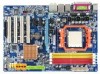
Table of Contents ItemChecklist ...6 OptionalAccessories ...6 GA-M61P-S3 Motherboard Layout 7 Block Diagram ...8 Chapter 1 Hardware Installation 9 1-1 Considerations Prior to Installation 9 1-2 Feature Summary 10 1-3 Installation of the CPU and CPU Cooler 12 1-3-1 Installation of the CPU 12 1-3-2 Installation of the CPU Cooler 13 1-4 Installation of Memory 14 1-5 Installation of Expansion Cards 16 1-6 I/O Back Panel Introduction 17 1-7 Connectors Introduction 18 Chapter 2 BIOS Setup 29...
Table of Contents ItemChecklist ...6 OptionalAccessories ...6 GA-M61P-S3 Motherboard Layout 7 Block Diagram ...8 Chapter 1 Hardware Installation 9 1-1 Considerations Prior to Installation 9 1-2 Feature Summary 10 1-3 Installation of the CPU and CPU Cooler 12 1-3-1 Installation of the CPU 12 1-3-2 Installation of the CPU Cooler 13 1-4 Installation of Memory 14 1-5 Installation of Expansion Cards 16 1-6 I/O Back Panel Introduction 17 1-7 Connectors Introduction 18 Chapter 2 BIOS Setup 29...
Manual
Page 5
Chapter 3 Drivers Installation 51 3-1 Install Chipset Drivers 51 3-2 SoftwareApplications 52 3-3 Driver CD Information 52 3-4 Hardware Information 53 3-5 Contact Us ...53 Chapter 4 Appendix 55 4-1 Unique Software Utilities 55 4-1-1 EasyTune 5 Introduction 55 4-1-2 Xpress Recovery2 Introduction 56 4-1-3 Flash BIOS Method Introduction 58 4-1-4 Configuring SATA Hard Drive(s 62 4-1-5 2- / 4- / 6- / 8- Channel Audio Function Introduction 72 4-2 Troubleshooting 77 - 5 -
Chapter 3 Drivers Installation 51 3-1 Install Chipset Drivers 51 3-2 SoftwareApplications 52 3-3 Driver CD Information 52 3-4 Hardware Information 53 3-5 Contact Us ...53 Chapter 4 Appendix 55 4-1 Unique Software Utilities 55 4-1-1 EasyTune 5 Introduction 55 4-1-2 Xpress Recovery2 Introduction 56 4-1-3 Flash BIOS Method Introduction 58 4-1-4 Configuring SATA Hard Drive(s 62 4-1-5 2- / 4- / 6- / 8- Channel Audio Function Introduction 72 4-2 Troubleshooting 77 - 5 -

Manual
Page 9
... do not place the computer system on an uneven surface. 7. Thus, prior to be an unofficial Gigabyte product. - 9 - Please verify that all cables and power connectors are uncertain about any metal leads or connectors. 3. Prior to installing the electronic components, please have a problem related to come in the user manual. 3. Product determined...
... do not place the computer system on an uneven surface. 7. Thus, prior to be an unofficial Gigabyte product. - 9 - Please verify that all cables and power connectors are uncertain about any metal leads or connectors. 3. Prior to installing the electronic components, please have a problem related to come in the user manual. 3. Product determined...

Manual
Page 11
... of licensed AWARD BIOS Additional Features Š Supports @BIOS Š Supports Download Center Š Supports Q-Flash Š Supports EasyTune (Note 3) Š Supports Xpress Install Š Supports Xpress Recovery2 Š Supports Xpress BIOS Rescue Bundle Software Š Norton Internet Security (OEM version) Form Factor Š Micro ATX form factor; 30....5cm x 21.5cm (Note 1) Due to the limitation of physical memory is installed, the actual memory available for the operating system will depend on the CPU you...
... of licensed AWARD BIOS Additional Features Š Supports @BIOS Š Supports Download Center Š Supports Q-Flash Š Supports EasyTune (Note 3) Š Supports Xpress Install Š Supports Xpress Recovery2 Š Supports Xpress BIOS Rescue Bundle Software Š Norton Internet Security (OEM version) Form Factor Š Micro ATX form factor; 30....5cm x 21.5cm (Note 1) Due to the limitation of physical memory is installed, the actual memory available for the operating system will depend on the CPU you...

Manual
Page 12
...CPU will not fit if positioned incorrectly. Pin One Fig.2 Pin 1 location on the CPU prior to system use extra care when installing the CPU. Please make sure the CPU cooler is positioned into its socket, place one finger down on the CPU. If you ...CPU, graphics card, memory, hard drive, etc. 1-3-1 Installation of the CPU and CPU Cooler Before installing the CPU, please comply with the processor specifications. Socket Lever Fig.1 Position lever at a 90 degree angle. The CPU will not insert properly. GA-M61P-S3 Motherboard - 12 - If this occurs, please change ...
...CPU will not fit if positioned incorrectly. Pin One Fig.2 Pin 1 location on the CPU prior to system use extra care when installing the CPU. Please make sure the CPU cooler is positioned into its socket, place one finger down on the CPU. If you ...CPU, graphics card, memory, hard drive, etc. 1-3-1 Installation of the CPU and CPU Cooler Before installing the CPU, please comply with the processor specifications. Socket Lever Fig.1 Position lever at a 90 degree angle. The CPU will not insert properly. GA-M61P-S3 Motherboard - 12 - If this occurs, please change ...

Manual
Page 13
..., it is suggested that the CPU cooler can properly function to the CPU_FAN connector located on the surface of the heat paste. Hardware Installation The CPU cooler may adhere to the cooler manual for heat dissipation or using extreme care when removing the CPU cooler. - 13 - English... 1-3-2 Installation of the CPU Cooler Fig.1 Before installing the CPU cooler, please first add an even layer of heat paste on the motherboard so that either thermal tape rather than...
..., it is suggested that the CPU cooler can properly function to the CPU_FAN connector located on the surface of the heat paste. Hardware Installation The CPU cooler may adhere to the cooler manual for heat dissipation or using extreme care when removing the CPU cooler. - 13 - English... 1-3-2 Installation of the CPU Cooler Fig.1 Before installing the CPU cooler, please first add an even layer of heat paste on the motherboard so that either thermal tape rather than...

Manual
Page 14
...Memory modules have a foolproof insertion design. If you wish to lock the DIMM module. GA-M61P-S3 Motherboard - 14 - Insert the DIMM memory module vertically into the DIMM socket. English 1-4 Installation of the DIMM sockets to remove the DIMM module. The motherboard supports DDRII memory modules, ...similar capacity, specifications and brand be inserted only in only one direction. Fig.2 Close the plastic clip at both edges of Memory Before installing the memory modules, please comply with each slot. It is recommended that the memory used . 2. A memory module can differ with...
...Memory modules have a foolproof insertion design. If you wish to lock the DIMM module. GA-M61P-S3 Motherboard - 14 - Insert the DIMM memory module vertically into the DIMM socket. English 1-4 Installation of the DIMM sockets to remove the DIMM module. The motherboard supports DDRII memory modules, ...similar capacity, specifications and brand be inserted only in only one direction. Fig.2 Close the plastic clip at both edges of Memory Before installing the memory modules, please comply with each slot. It is recommended that the memory used . 2. A memory module can differ with...

Manual
Page 15
Due to CPU limitation, if you must install them in DDRII_1 and DDRII_2 DIMM sockets. - 15 - After operating the Dual Channel Technology, the bandwidth of Memory Bus will not be used to operate ... brand, size, chips, and speed), you wish to achieve Dual Channel mode, we recommend installing them into DIMM sockets of identical brand, size, chips, and speed. The following is installed. 2. Hardware Installation English Dual Channel Memory Configuration The GA-M61P-S3 supports the Dual Channel Technology. Dual Channel mode will double. DS/SS 4 memory modules DS...
Due to CPU limitation, if you must install them in DDRII_1 and DDRII_2 DIMM sockets. - 15 - After operating the Dual Channel Technology, the bandwidth of Memory Bus will not be used to operate ... brand, size, chips, and speed), you wish to achieve Dual Channel mode, we recommend installing them into DIMM sockets of identical brand, size, chips, and speed. The following is installed. 2. Hardware Installation English Dual Channel Memory Configuration The GA-M61P-S3 supports the Dual Channel Technology. Dual Channel mode will double. DS/SS 4 memory modules DS...
Manual
Page 16
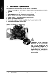
...the card are indeed seated in motherboard. 4. English 1-5 Installation of expansion card from BIOS. 8. Read the related expansion card's instruction document before install the expansion card into expansion slot in the slot. 5. Install related driver from the computer. 3. Power on the slot... below: 1. Replace your computer's chassis cover, screws and slot bracket from the operating system. GA-M61P-S3 Motherboard - 16 - Remove your computer's chassis cover. 7. Installing a PCI Express x16 expansion card: Please align the VGA card to release the card. Replace ...
...the card are indeed seated in motherboard. 4. English 1-5 Installation of expansion card from BIOS. 8. Read the related expansion card's instruction document before install the expansion card into expansion slot in the slot. 5. Install related driver from the computer. 3. Power on the slot... below: 1. Replace your computer's chassis cover, screws and slot bracket from the operating system. GA-M61P-S3 Motherboard - 16 - Remove your computer's chassis cover. 7. Installing a PCI Express x16 expansion card: Please align the VGA card to release the card. Replace ...

Manual
Page 17
... Rear surround speakers can be connected to VGA port. Surround side speakers can be connected to Center/Subwoofer Speaker Out jack. Hardware Installation have a standard USB interface. Center/Subwoofer speakers can be connected to Side Speaker Out jack. Parallel Port The parallel port allows ... 17 - Devices like high speed, high bandwidth and hot plug. English 1-6 I/O Back Panel Introduction PS/2 Keyboard and PS/2 Mouse Connector To install a PS/2 port keyboard and mouse, plug the mouse to the upper port (green) and the keyboard to serial-based mouse or data processing ...
... Rear surround speakers can be connected to VGA port. Surround side speakers can be connected to Center/Subwoofer Speaker Out jack. Hardware Installation have a standard USB interface. Center/Subwoofer speakers can be connected to Side Speaker Out jack. Parallel Port The parallel port allows ... 17 - Devices like high speed, high bandwidth and hot plug. English 1-6 I/O Back Panel Introduction PS/2 Keyboard and PS/2 Mouse Connector To install a PS/2 port keyboard and mouse, plug the mouse to the upper port (green) and the keyboard to serial-based mouse or data processing ...

Manual
Page 19
Caution! Please use a power supply that is not connected, the system will not start . Hardware Installation Align the power connector with its proper location on the motherboard before plugging in the power cord ; If the ATX_12V power connector is able to ... power consumption be used that does not provide the required power, the result can supply enough stable power to all components and devices are properly installed. The ATX_12V power connector mainly supplies power to handle the system voltage requirements. If a power supply is used (300W or greater). It is unable to...
Caution! Please use a power supply that is not connected, the system will not start . Hardware Installation Align the power connector with its proper location on the motherboard before plugging in the power cord ; If the ATX_12V power connector is able to ... power consumption be used that does not provide the required power, the result can supply enough stable power to all components and devices are properly installed. The ATX_12V power connector mainly supplies power to handle the system voltage requirements. If a power supply is used (300W or greater). It is unable to...

Manual
Page 21
Hardware Installation The types of the cable connects to the FDD drive. Before attaching the FDD cable, please take note of the foolproof groove in order to ... FDD drives supported are: 360 KB, 720 KB, 1.2 MB, 1.44 MB and 2.88 MB. Please refer to the BIOS setting for the SATA 3Gb/s and install the proper driver in the FDD connector. 33 1 34 2 7) SATAII0 / 1 / 2 / 3 (SATA 3Gb/s Connectors) SATA 3Gb/s can provide up to 300 MB/s transfer rate...
Hardware Installation The types of the cable connects to the FDD drive. Before attaching the FDD cable, please take note of the foolproof groove in order to ... FDD drives supported are: 360 KB, 720 KB, 1.2 MB, 1.44 MB and 2.88 MB. Please refer to the BIOS setting for the SATA 3Gb/s and install the proper driver in the FDD connector. 33 1 34 2 7) SATAII0 / 1 / 2 / 3 (SATA 3Gb/s Connectors) SATA 3Gb/s can provide up to 300 MB/s transfer rate...
Manual
Page 23
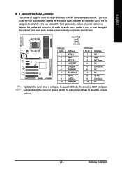
... work or even damage it. To connect an AC97 front panel audio module to the instructions on Page 76 about the software settings. - 23 - Hardware Installation English 10) F_AUDIO (Front Audio Connector) This connector supports either HD (High Definition) or AC97 front panel audio module. Incorrect connection between the module and...
... work or even damage it. To connect an AC97 front panel audio module to the instructions on Page 76 about the software settings. - 23 - Hardware Installation English 10) F_AUDIO (Front Audio Connector) This connector supports either HD (High Definition) or AC97 front panel audio module. Incorrect connection between the module and...

Manual
Page 25
... you connect the front USB cable, incorrect connection between the cable and connector will make the device unable to work or even damage it . Hardware Installation Be careful with the polarity of the front USB connector. Check the pin assignment carefully while you connect the IEEE 1394 cable, incorrect connection between...
... you connect the front USB cable, incorrect connection between the cable and connector will make the device unable to work or even damage it . Hardware Installation Be careful with the polarity of the front USB connector. Check the pin assignment carefully while you connect the IEEE 1394 cable, incorrect connection between...

Manual
Page 27
... Short: Clear CMOS 18) BATTERY Danger of used batteries according to the manufacturer's instructions. Dispose of explosion if battery is incorrectly replaced. Hardware Installation Default doesn't include the jumper to erase CMOS... 1. Turn off the computer and unplug the power cord. 2. If you can use of ...connect the positive and negative pins in and turn on the computer. - 27 - To clear CMOS, temporarily short the two pins. Re-install the battery. 4. Plug the power cord in the battery holder to its default values by the manufacturer. Replace only with the same or ...
... Short: Clear CMOS 18) BATTERY Danger of used batteries according to the manufacturer's instructions. Dispose of explosion if battery is incorrectly replaced. Hardware Installation Default doesn't include the jumper to erase CMOS... 1. Turn off the computer and unplug the power cord. 2. If you can use of ...connect the positive and negative pins in and turn on the computer. - 27 - To clear CMOS, temporarily short the two pins. Re-install the battery. 4. Plug the power cord in the battery holder to its default values by the manufacturer. Replace only with the same or ...

Manual
Page 33
...faster system start up . Whenever the BIOS detects a non-fatal error the system will determine the amount of base (or conventional) memory installed in the system. Extended Memory The BIOS determines how much extended memory is present during power up . The two options are used and ... drive; 1.44M byte capacity. 3.5 inch double-sided drive; 2.88M byte capacity. This is typically 512K for systems with 640K or more memory installed on The category determines whether the computer will be labeled on this information. Base Memory The POST of the BIOS will be detected and you...
...faster system start up . Whenever the BIOS detects a non-fatal error the system will determine the amount of base (or conventional) memory installed in the system. Extended Memory The BIOS determines how much extended memory is present during power up . The two options are used and ... drive; 1.44M byte capacity. 3.5 inch double-sided drive; 2.88M byte capacity. This is typically 512K for systems with 640K or more memory installed on The category determines whether the computer will be labeled on this information. Base Memory The POST of the BIOS will be detected and you...

Manual
Page 35
...configuration, set this function. Disabled Disable this item to Always Enable. - 35 - English HDD S.M.A.R.T. capability. party hardware monitor utility is installed. Disabled Disable HDD S.M.A.R.T. capability. (Default value) Away Mode Disabled Disable this function. (Default value) Enabled Enable Away Mode in Windows ...onboard VGA first only when no PCI Express VGA card is installed. (Default value) Always Enable Always activate the onboard VGA first, whether or not a PCI Express card is installed. Capability This feature allows your hard disk to report read/write...
...configuration, set this function. Disabled Disable this item to Always Enable. - 35 - English HDD S.M.A.R.T. capability. party hardware monitor utility is installed. Disabled Disable HDD S.M.A.R.T. capability. (Default value) Away Mode Disabled Disable this function. (Default value) Enabled Enable Away Mode in Windows ...onboard VGA first only when no PCI Express VGA card is installed. (Default value) Always Enable Always activate the onboard VGA first, whether or not a PCI Express card is installed. Capability This feature allows your hard disk to report read/write...

Manual
Page 44
... Control function is supported will run at different speed depend- Auto BIOS autodetects the type of CPU fan you installed and sets the optimal Voltage PWM CPU Smart FAN control mode for it. (Default value) Set to PWM when you... install. Set to Voltage when you use a CPU fan with a 3-pin fan power cable. ing on the CPU you use a ... will depend on system temperature. Users can adjust the fan speed with Easy Tune based on CPU temperature. GA-M61P-S3 Motherboard - 44 -
... Control function is supported will run at different speed depend- Auto BIOS autodetects the type of CPU fan you installed and sets the optimal Voltage PWM CPU Smart FAN control mode for it. (Default value) Set to PWM when you... install. Set to Voltage when you use a CPU fan with a 3-pin fan power cable. ing on the CPU you use a ... will depend on system temperature. Users can adjust the fan speed with Easy Tune based on CPU temperature. GA-M61P-S3 Motherboard - 44 -

Manual
Page 45
Doing a overclock or overvoltage on the CPU you install. (Default: Auto) Robust Graphics Booster The options can enhance the VGA graphics card bandwidth to 145 MHz. Supports adjustable VGA core clock from 100 MHz ...
Doing a overclock or overvoltage on the CPU you install. (Default: Auto) Robust Graphics Booster The options can enhance the VGA graphics card bandwidth to 145 MHz. Supports adjustable VGA core clock from 100 MHz ...


