
Manual
Page 4
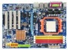
Table of Contents ItemChecklist ...6 OptionalAccessories ...6 GA-M61P-S3 Motherboard Layout 7 Block Diagram ...8 Chapter 1 Hardware Installation 9 1-1 Considerations Prior to Installation 9 1-2 Feature Summary 10 1-3 Installation of the CPU and CPU Cooler 12 1-3-1 Installation of the CPU 12 1-3-2 Installation of the CPU Cooler 13 1-4 Installation of Memory 14 1-5 Installation of Expansion Cards 16 1-6 I/O Back Panel Introduction 17 1-7 Connectors...
Table of Contents ItemChecklist ...6 OptionalAccessories ...6 GA-M61P-S3 Motherboard Layout 7 Block Diagram ...8 Chapter 1 Hardware Installation 9 1-1 Considerations Prior to Installation 9 1-2 Feature Summary 10 1-3 Installation of the CPU and CPU Cooler 12 1-3-1 Installation of the CPU 12 1-3-2 Installation of the CPU Cooler 13 1-4 Installation of Memory 14 1-5 Installation of Expansion Cards 16 1-6 I/O Back Panel Introduction 17 1-7 Connectors...
Manual
Page 8
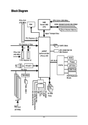
Block Diagram PCIe CLK (100 MHz) VGA AMD Socket AM2 CPU CPU CLK+/-(200 MHz) DDRII 800/667/533/400 MHz DIMM Dual Channel Memory Hyper Transport Bus PCI Express x16 LAN RJ45 PCI Express x1 Bus x1 x1 PCIe CLK (100 MHz) 1 PCI Express x2 RTL8211 PCI Bus TSB43AB23 4 SATA 3Gb/s nVIDIA® GeForce 6100/ nForce 430 LPC BUS ATA 33/66/100/133 IDE Channel BIOS Floppy IT8716 LPT Port COM Ports CODEC PS/2 Keyboard/ Mouse 3 IEEE 1394a Surround Speaker Out Center/Subwoofer Spear Out Side Speaker Out MIC Line-Out Line-In SPDIF In SPDIF Out 4 PCI PCI CLK (33 MHz) 10 USB Ports - 8 -
Block Diagram PCIe CLK (100 MHz) VGA AMD Socket AM2 CPU CPU CLK+/-(200 MHz) DDRII 800/667/533/400 MHz DIMM Dual Channel Memory Hyper Transport Bus PCI Express x16 LAN RJ45 PCI Express x1 Bus x1 x1 PCIe CLK (100 MHz) 1 PCI Express x2 RTL8211 PCI Bus TSB43AB23 4 SATA 3Gb/s nVIDIA® GeForce 6100/ nForce 430 LPC BUS ATA 33/66/100/133 IDE Channel BIOS Floppy IT8716 LPT Port COM Ports CODEC PS/2 Keyboard/ Mouse 3 IEEE 1394a Surround Speaker Out Center/Subwoofer Spear Out Side Speaker Out MIC Line-Out Line-In SPDIF In SPDIF Out 4 PCI PCI CLK (33 MHz) 10 USB Ports - 8 -

Manual
Page 10
...0, RAID 1, RAID 0+1 and RAID 5 for Serial ATA O.S Support Š Microsoft Windows 2000/XP Memory Š 4 DDRII DIMM memory slots (supports up to 16 GB memory)(Note 1) Š Supports dual channel DDRII 800/667/533/400 DIMMs Š Supports 1.8V DDRII ...1 COMB connector Š 3 USB 2.0/1.1 connectors for additional 6 USB 2.0/1.1 ports by cable Š 1 power LED connector Š 1 Chassis Intrusion connector GA-M61P-S3 Motherboard - 10 - TSB43AB23 chip Š 3 IEEE 1394a ports Storage Š nVIDIA® GeForce 6100/nForce 430 chipset - 1 FDD connector, allowing connection ...
...0, RAID 1, RAID 0+1 and RAID 5 for Serial ATA O.S Support Š Microsoft Windows 2000/XP Memory Š 4 DDRII DIMM memory slots (supports up to 16 GB memory)(Note 1) Š Supports dual channel DDRII 800/667/533/400 DIMMs Š Supports 1.8V DDRII ...1 COMB connector Š 3 USB 2.0/1.1 connectors for additional 6 USB 2.0/1.1 ports by cable Š 1 power LED connector Š 1 Chassis Intrusion connector GA-M61P-S3 Motherboard - 10 - TSB43AB23 chip Š 3 IEEE 1394a ports Storage Š nVIDIA® GeForce 6100/nForce 430 chipset - 1 FDD connector, allowing connection ...

Manual
Page 11
... Norton Internet Security (OEM version) Form Factor Š Micro ATX form factor; 30.5cm x 21.5cm (Note 1) Due to the limitation of physical memory is supported will depend on the CPU you install. (Note 3) EasyTune functions may vary depending on different motherboards. - 11 - Windows 64-bit operating system ...doesn't have such limitation. (Note 2) Whether the CPU Smart FAN Control function is installed, the actual memory available for the operating system will be less than 4 GB of Windows 32-bit operating system, when more than 4 GB;
... Norton Internet Security (OEM version) Form Factor Š Micro ATX form factor; 30.5cm x 21.5cm (Note 1) Due to the limitation of physical memory is supported will depend on the CPU you install. (Note 3) EasyTune functions may vary depending on different motherboards. - 11 - Windows 64-bit operating system ...doesn't have such limitation. (Note 2) Whether the CPU Smart FAN Control function is installed, the actual memory available for the operating system will be less than 4 GB of Windows 32-bit operating system, when more than 4 GB;

Manual
Page 12
...location on the socket as shown in Fig. 2. Gently place the CPU into position making sure that the motherboard supports the CPU. 2. GA-M61P-S3 Motherboard - 12 - English 1-3 Installation of the CPU and CPU Cooler Before installing the CPU, please comply with the processor specifications. Please ... motherboard) prior to set beyond the proper specifications, please do so according to your hardware specifications including the CPU, graphics card, memory, hard drive, etc. 1-3-1 Installation of the CPU Check the CPU pins to system use extra care when installing the CPU. Socket...
...location on the socket as shown in Fig. 2. Gently place the CPU into position making sure that the motherboard supports the CPU. 2. GA-M61P-S3 Motherboard - 12 - English 1-3 Installation of the CPU and CPU Cooler Before installing the CPU, please comply with the processor specifications. Please ... motherboard) prior to set beyond the proper specifications, please do so according to your hardware specifications including the CPU, graphics card, memory, hard drive, etc. 1-3-1 Installation of the CPU Check the CPU pins to system use extra care when installing the CPU. Socket...

Manual
Page 14
... the installation steps when you are designed so that memory of similar capacity, specifications and brand be used can be installed in only one direction. It is supported by the motherboard. Then push it down. GA-M61P-S3 Motherboard - 14 - Please make sure that the computer... power is switched off to lock the DIMM module. Memory modules have a foolproof insertion design. Before installing or removing memory modules, please make sure that the memory used is recommended that they ...
... the installation steps when you are designed so that memory of similar capacity, specifications and brand be used can be installed in only one direction. It is supported by the motherboard. Then push it down. GA-M61P-S3 Motherboard - 14 - Please make sure that the computer... power is switched off to lock the DIMM module. Memory modules have a foolproof insertion design. Before installing or removing memory modules, please make sure that the memory used is recommended that they ...

Manual
Page 15
... CPU limitation, if you must install them in DDRII_1 and DDRII_2 DIMM sockets. - 15 - English Dual Channel Memory Configuration The GA-M61P-S3 supports the Dual Channel Technology. To enable Dual Channel mode with four memory modules, it is a Dual Channel Memory configuration table: (DS: Double Side, SS: Single Side, "--": Empty) DIMM Socket DDRII_1 DDRII_2 DDRII_...
... CPU limitation, if you must install them in DDRII_1 and DDRII_2 DIMM sockets. - 15 - English Dual Channel Memory Configuration The GA-M61P-S3 supports the Dual Channel Technology. To enable Dual Channel mode with four memory modules, it is a Dual Channel Memory configuration table: (DS: Double Side, SS: Single Side, "--": Empty) DIMM Socket DDRII_1 DDRII_2 DDRII_...

Manual
Page 32
... [None] [None] [None] [None] [None] [None] Drive A Floppy 3 Mode Support [1.44M, 3.5"] [Disabled] Halt On [All, But Keyboard] Base Memory Extended Memory 640K 447M KLJI: Move Enter: Select F5: Previous Values +/-/PU/PD: Value F10: Save F6: Fail-Safe Defaults ESC: Exit F1: General Help F7: Optimized...2098 Time The times format in the month) Year The year, from Sun to automatically detect IDE/SATA devices during POST. (default) GA-M61P-S3 Motherboard - 32 - IDE Channel 0, Master/Slave IDE/SATA Device Setup. IDE Channel 0 Master/Slave IDE HDD Auto-Detection Press "Enter...
... [None] [None] [None] [None] [None] [None] Drive A Floppy 3 Mode Support [1.44M, 3.5"] [Disabled] Halt On [All, But Keyboard] Base Memory Extended Memory 640K 447M KLJI: Move Enter: Select F5: Previous Values +/-/PU/PD: Value F10: Save F6: Fail-Safe Defaults ESC: Exit F1: General Help F7: Optimized...2098 Time The times format in the month) Year The year, from Sun to automatically detect IDE/SATA devices during POST. (default) GA-M61P-S3 Motherboard - 32 - IDE Channel 0, Master/Slave IDE/SATA Device Setup. IDE Channel 0 Master/Slave IDE HDD Auto-Detection Press "Enter...

Manual
Page 33
... during power up . No Errors All Errors The system boot will not stop for any error that has been installed in the CPU's memory address map. - 33 - Cylinder Number of cylinders Head Number of heads Precomp Write precomp Landing Zone Sector Landing zone Number of sectors ...Drive A The category identifies the types of floppy disk drive A that may be detected and you will stop for faster system start up . Memory The category is display-only which is Enabled). 720K, 3.5" 1.44M, 3.5" 2.88M, 3.5" 3.5 inch double-sided drive; 720K byte capacity . 3.5 inch double...
... during power up . No Errors All Errors The system boot will not stop for any error that has been installed in the CPU's memory address map. - 33 - Cylinder Number of cylinders Head Number of heads Precomp Write precomp Landing Zone Sector Landing zone Number of sectors ...Drive A The category identifies the types of floppy disk drive A that may be detected and you will stop for faster system start up . Memory The category is display-only which is Enabled). 720K, 3.5" 1.44M, 3.5" 2.88M, 3.5" 3.5 inch double-sided drive; 720K byte capacity . 3.5 inch double...

Manual
Page 36
.../s controller. (Default value) Disabled Disable this function. GA-M61P-S3 Motherboard - 36 - English 2-3 Integrated Peripherals CMOS Setup Utility-Copyright (C) 1984-2006 Award Software Integrated Peripherals ` Serial-ATA RAID Config On-Chip IDE Channel0 On-Chip MAC Lan NV Serial-ATA Controller IDE Prefetch Mode USB Memory Type Onboard Audio Function Onboard 1394 ` SMART LAN...
.../s controller. (Default value) Disabled Disable this function. GA-M61P-S3 Motherboard - 36 - English 2-3 Integrated Peripherals CMOS Setup Utility-Copyright (C) 1984-2006 Award Software Integrated Peripherals ` Serial-ATA RAID Config On-Chip IDE Channel0 On-Chip MAC Lan NV Serial-ATA Controller IDE Prefetch Mode USB Memory Type Onboard Audio Function Onboard 1394 ` SMART LAN...

Manual
Page 37
... the second SATA 3Gb/s controller. (Default value) Disabled Disable this function. IDE Prefetch Mode Enabled Enable IDE data buffer to base memory(640K). On-Chip MAC Lan Auto Auto-detect onboard LAN chip function. (Default value) Disabled Disable onboard LAN chip function. All...onboard SATA 3Gb/s controllers. (Default value) Disabled Disable the onboard SATA 3Gb/s controllers. USB Memory Type SHADOW Set USB memory type to SHADOW. (Default value) Base Memory(640K) Set USB memory type to enhance HDD transfer speed. (Default value) Disabled Disable IDE data buffer for the ...
... the second SATA 3Gb/s controller. (Default value) Disabled Disable this function. IDE Prefetch Mode Enabled Enable IDE data buffer to base memory(640K). On-Chip MAC Lan Auto Auto-detect onboard LAN chip function. (Default value) Disabled Disable onboard LAN chip function. All...onboard SATA 3Gb/s controllers. (Default value) Disabled Disable the onboard SATA 3Gb/s controllers. USB Memory Type SHADOW Set USB memory type to SHADOW. (Default value) Base Memory(640K) Set USB memory type to enhance HDD transfer speed. (Default value) Disabled Disable IDE data buffer for the ...

Manual
Page 45
... from +1%~+50%. menu items are for the graphics chip and is available only when the Robust Graphics Booster option is dependent on CPU, chipsets and memory modules may result in system instability or corruption. BIOS Setup Supports adjustable VGA core clock from 100 MHz to +0.025V~+0.200V. - 45 - VGA Core Clock...
... from +1%~+50%. menu items are for the graphics chip and is available only when the Robust Graphics Booster option is dependent on CPU, chipsets and memory modules may result in system instability or corruption. BIOS Setup Supports adjustable VGA core clock from 100 MHz to +0.025V~+0.200V. - 45 - VGA Core Clock...

Manual
Page 46
Supports adjustable CPU voltage from 1.850V to +0.025V~+0.200V. GA-M61P-S3 Motherboard - 46 - DDR2 Voltage Control Please note that by overclocking your CPU's normal vcore voltage. Supports adjustable DDR2 voltage from 0.8000V to 1.5500V. (Default value: ... to 2.400V. (Default value: Auto) CPU Voltage Control Please note that by overclocking your system through the increase of the CPU voltage, damage to the memory may occur. English Chipset Voltage Control Set the voltage settings for Chipset.
Supports adjustable CPU voltage from 1.850V to +0.025V~+0.200V. GA-M61P-S3 Motherboard - 46 - DDR2 Voltage Control Please note that by overclocking your CPU's normal vcore voltage. Supports adjustable DDR2 voltage from 0.8000V to 1.5500V. (Default value: ... to 2.400V. (Default value: Auto) CPU Voltage Control Please note that by overclocking your system through the increase of the CPU voltage, damage to the memory may occur. English Chipset Voltage Control Set the voltage settings for Chipset.

Manual
Page 55
... display LEDs Shows the current functions status 9. Help button Display EasyTuneTM 5 Help file 11. Featuring several powerful yet easy to GIGABYTE website 10. GO Confirmation and Execution button 6. English Chapter 4 Appendix 4-1 Unique Software Utilities (Not all model support these Unique... North-Bridge Chipset cooling fan, 4) PC health for enhancing system performance, 2) C.I .B. GIGABYTE Logo Log on different motherboards. - 55 - and M.I .B. for special enhancement for CPU and Memory, 3) Smart-Fan control for managing fan speed control of CPU frequency 8. "Easy Mode"...
... display LEDs Shows the current functions status 9. Help button Display EasyTuneTM 5 Help file 11. Featuring several powerful yet easy to GIGABYTE website 10. GO Confirmation and Execution button 6. English Chapter 4 Appendix 4-1 Unique Software Utilities (Not all model support these Unique... North-Bridge Chipset cooling fan, 4) PC health for enhancing system performance, 2) C.I .B. GIGABYTE Logo Log on different motherboards. - 55 - and M.I .B. for special enhancement for CPU and Memory, 3) Smart-Fan control for managing fan speed control of CPU frequency 8. "Easy Mode"...

Manual
Page 56
...Xpress Recovery2 Initial access by booting from CD-ROM and subsequent access by booting from CD/DVD: Press any key to enter Xpress Recovery2. GA-M61P-S3 Motherboard - 56 - Save the settings and exit the BIOS Setup. Insert the provided driver CD into your hard disk. Award Modular BIOS ...for the first time, it will appear in the future. 2. Intel x86 platforms 2. System storage capacity and the reading/writing speed of system memory 3. System requirements: 1. It is recommended that Xpress Recovery2 be made by pressing the key in the bottom left corner of the screen. ...
...Xpress Recovery2 Initial access by booting from CD-ROM and subsequent access by booting from CD/DVD: Press any key to enter Xpress Recovery2. GA-M61P-S3 Motherboard - 56 - Save the settings and exit the BIOS Setup. Insert the provided driver CD into your hard disk. Award Modular BIOS ...for the first time, it will appear in the future. 2. Intel x86 platforms 2. System storage capacity and the reading/writing speed of system memory 3. System requirements: 1. It is recommended that Xpress Recovery2 be made by pressing the key in the bottom left corner of the screen. ...

Manual
Page 63
...-2006 Award Software Integrated Peripherals Serial-ATA RAID Config On-Chip IDE Channel0 On-Chip MAC Lan NV Serial-ATA Controller IDE Prefetch Mode USB Memory Type Onboard Audio Function Onboard 1394 SMART LAN OnBoard LAN Boot ROM Onboard Serial Port 1 Onboard Serial Port 2 Onboard Parallel Port Parallel Port Mode x ECP...
...-2006 Award Software Integrated Peripherals Serial-ATA RAID Config On-Chip IDE Channel0 On-Chip MAC Lan NV Serial-ATA Controller IDE Prefetch Mode USB Memory Type Onboard Audio Function Onboard 1394 SMART LAN OnBoard LAN Boot ROM Onboard Serial Port 1 Onboard Serial Port 2 Onboard Parallel Port Parallel Port Mode x ECP...
Manual
Page 65
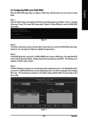
.... English (3) Configuring RAID set the Striping Block size. The supported RAID modes include Mirroring (default), Striping, Stripe Mirroring, Spanning and RAID 5. Step 1: After the POST memory test begins and before the operating system boot begins, look for a message which says "Press F10 to select a RAID mode. Hit the F10 key to...
.... English (3) Configuring RAID set the Striping Block size. The supported RAID modes include Mirroring (default), Striping, Stripe Mirroring, Spanning and RAID 5. Step 1: After the POST memory test begins and before the operating system boot begins, look for a message which says "Press F10 to select a RAID mode. Hit the F10 key to...


