
Manual
Page 4
Table of Contents ItemChecklist ...6 OptionalAccessories ...6 GA-M61P-S3 Motherboard Layout 7 Block Diagram ...8 Chapter 1 Hardware Installation 9 1-1 Considerations Prior to Installation 9 1-2 Feature Summary 10 1-3 Installation of the CPU and CPU Cooler 12 1-3-1 Installation of the CPU 12 1-3-2 Installation of the CPU Cooler 13 1-4 Installation of Memory 14 1-5 Installation of Expansion Cards 16 1-6 I/O Back Panel Introduction 17 1-7 Connectors Introduction 18 Chapter...
Table of Contents ItemChecklist ...6 OptionalAccessories ...6 GA-M61P-S3 Motherboard Layout 7 Block Diagram ...8 Chapter 1 Hardware Installation 9 1-1 Considerations Prior to Installation 9 1-2 Feature Summary 10 1-3 Installation of the CPU and CPU Cooler 12 1-3-1 Installation of the CPU 12 1-3-2 Installation of the CPU Cooler 13 1-4 Installation of Memory 14 1-5 Installation of Expansion Cards 16 1-6 I/O Back Panel Introduction 17 1-7 Connectors Introduction 18 Chapter...
Manual
Page 8
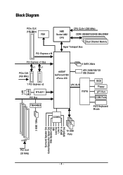
Block Diagram PCIe CLK (100 MHz) VGA AMD Socket AM2 CPU CPU CLK+/-(200 MHz) DDRII 800/667/533/400 MHz DIMM Dual Channel Memory Hyper Transport Bus PCI Express x16 LAN RJ45 PCI Express x1 Bus x1 x1 PCIe CLK (100 MHz) 1 PCI Express x2 RTL8211 PCI Bus TSB43AB23 4 SATA 3Gb/s nVIDIA® GeForce 6100/ nForce 430 LPC BUS ATA 33/66/100/133 IDE Channel BIOS Floppy IT8716 LPT Port COM Ports CODEC PS/2 Keyboard/ Mouse 3 IEEE 1394a Surround Speaker Out Center/Subwoofer Spear Out Side Speaker Out MIC Line-Out Line-In SPDIF In SPDIF Out 4 PCI PCI CLK (33 MHz) 10 USB Ports - 8 -
Block Diagram PCIe CLK (100 MHz) VGA AMD Socket AM2 CPU CPU CLK+/-(200 MHz) DDRII 800/667/533/400 MHz DIMM Dual Channel Memory Hyper Transport Bus PCI Express x16 LAN RJ45 PCI Express x1 Bus x1 x1 PCIe CLK (100 MHz) 1 PCI Express x2 RTL8211 PCI Bus TSB43AB23 4 SATA 3Gb/s nVIDIA® GeForce 6100/ nForce 430 LPC BUS ATA 33/66/100/133 IDE Channel BIOS Floppy IT8716 LPT Port COM Ports CODEC PS/2 Keyboard/ Mouse 3 IEEE 1394a Surround Speaker Out Center/Subwoofer Spear Out Side Speaker Out MIC Line-Out Line-In SPDIF In SPDIF Out 4 PCI PCI CLK (33 MHz) 10 USB Ports - 8 -

Manual
Page 9
... prevent damage to the motherboard, please do not allow screws to wear an electrostatic discharge (ESD) cuff when handling electronic components (CPU, RAM). 4. If you are no leftover screws or metal components placed on the motherboard. Damage due to installation, please follow ... to installing the electronic components, please have a problem related to the use exceeding the permitted parameters. 6. Damage due to be an unofficial Gigabyte product. - 9 - Product determined to natural disaster, accident or human cause. 2. Please make sure there are uncertain about any metal leads...
... prevent damage to the motherboard, please do not allow screws to wear an electrostatic discharge (ESD) cuff when handling electronic components (CPU, RAM). 4. If you are no leftover screws or metal components placed on the motherboard. Damage due to installation, please follow ... to installing the electronic components, please have a problem related to the use exceeding the permitted parameters. 6. Damage due to be an unofficial Gigabyte product. - 9 - Product determined to natural disaster, accident or human cause. 2. Please make sure there are uncertain about any metal leads...

Manual
Page 10
English 1-2 Feature Summary CPU Š Socket AM2 for additional 2 ports by cable Š 1 power LED connector Š 1 Chassis Intrusion connector GA-M61P-S3 Motherboard - 10 - Supports data RAID 0, RAID 1, RAID 0+1 and RAID 5 for Serial ATA O.S Support Š Microsoft ...pin ATX power connector Š 1 4-pin ATX 12V power connector Š 1 floppy connector Š 1 IDE connector Š 4 SATA 3Gb/s connectors Š 1 CPU fan connector Š 1 system fan connector Š 1 front panel connector Š 1 front audio connector Š 1 CD In connector Š 1 S/PDIF In...
English 1-2 Feature Summary CPU Š Socket AM2 for additional 2 ports by cable Š 1 power LED connector Š 1 Chassis Intrusion connector GA-M61P-S3 Motherboard - 10 - Supports data RAID 0, RAID 1, RAID 0+1 and RAID 5 for Serial ATA O.S Support Š Microsoft ...pin ATX power connector Š 1 4-pin ATX 12V power connector Š 1 floppy connector Š 1 IDE connector Š 4 SATA 3Gb/s connectors Š 1 CPU fan connector Š 1 system fan connector Š 1 front panel connector Š 1 front audio connector Š 1 CD In connector Š 1 S/PDIF In...

Manual
Page 11
... Out) I/O Control Š IT8716 chip Hardware Monitor Š System voltage detection Š CPU / System temperature detection Š CPU / System fan speed detection Š CPU / System warning temperature Š CPU / System fan failure warning Š Supports CPU / System Smart Fan function (Note 2) BIOS Š 1 4 Mbit flash ROM Š...be less than 4 GB; Hardware Installation Windows 64-bit operating system doesn't have such limitation. (Note 2) Whether the CPU Smart FAN Control function is installed, the actual memory available for the operating system will depend on the...
... Out) I/O Control Š IT8716 chip Hardware Monitor Š System voltage detection Š CPU / System temperature detection Š CPU / System fan speed detection Š CPU / System warning temperature Š CPU / System fan failure warning Š Supports CPU / System Smart Fan function (Note 2) BIOS Š 1 4 Mbit flash ROM Š...be less than 4 GB; Hardware Installation Windows 64-bit operating system doesn't have such limitation. (Note 2) Whether the CPU Smart FAN Control function is installed, the actual memory available for the operating system will depend on the...

Manual
Page 12
... occur. 5. Rather than applying force, please change the insert direction of the motherboard) prior to the plane of the CPU. 3. GA-M61P-S3 Motherboard - 12 - Please set beyond the proper specifications, please do so according to the socket and gently lower it does not meet the required ...standards for the peripherals. Please take note of the CPU. Socket Lever Fig.1 Position lever at a 90 degree angle. Move the socket lever to the unlocked position as shown in Fig. 1 (90o to ...
... occur. 5. Rather than applying force, please change the insert direction of the motherboard) prior to the plane of the CPU. 3. GA-M61P-S3 Motherboard - 12 - Please set beyond the proper specifications, please do so according to the socket and gently lower it does not meet the required ...standards for the peripherals. Please take note of the CPU. Socket Lever Fig.1 Position lever at a 90 degree angle. Move the socket lever to the unlocked position as shown in Fig. 1 (90o to ...

Manual
Page 13
... function to the CPU_FAN connector located on the surface of the CPU. Install all the CPU cooler components (Please refer to the CPU as a result of hardening of the heat paste. Hardware Installation English 1-3-2 Installation of the CPU Cooler Fig.1 Before installing the CPU cooler, please first add an even layer of heat paste on...
... function to the CPU_FAN connector located on the surface of the CPU. Install all the CPU cooler components (Please refer to the CPU as a result of hardening of the heat paste. Hardware Installation English 1-3-2 Installation of the CPU Cooler Fig.1 Before installing the CPU cooler, please first add an even layer of heat paste on...

Manual
Page 15
...(DS: Double Side, SS: Single Side, "--": Empty) DIMM Socket DDRII_1 DDRII_2 DDRII_ 3 2 memory modules DS/SS DS/SS - - - - - - English Dual Channel Memory Configuration The GA-M61P-S3 supports the Dual Channel Technology. To enable Dual Channel mode with two memory modules (it is installed. 2. Due to achieve Dual Channel mode, we recommend... of identical brand, size, chips, and speed. After operating the Dual Channel Technology, the bandwidth of Memory Bus will not be used to CPU limitation, if you must install them in DDRII_1 and DDRII_2 DIMM sockets. - 15 -
...(DS: Double Side, SS: Single Side, "--": Empty) DIMM Socket DDRII_1 DDRII_2 DDRII_ 3 2 memory modules DS/SS DS/SS - - - - - - English Dual Channel Memory Configuration The GA-M61P-S3 supports the Dual Channel Technology. To enable Dual Channel mode with two memory modules (it is installed. 2. Due to achieve Dual Channel mode, we recommend... of identical brand, size, chips, and speed. After operating the Dual Channel Technology, the bandwidth of Memory Bus will not be used to CPU limitation, if you must install them in DDRII_1 and DDRII_2 DIMM sockets. - 15 -

Manual
Page 19
..., the power supply can lead to an unstable system or a system that is not connected, the system will not start . It is able to the CPU. Align the power connector with its proper location on the motherboard and connect tightly.
..., the power supply can lead to an unstable system or a system that is not connected, the system will not start . It is able to the CPU. Align the power connector with its proper location on the motherboard and connect tightly.

Manual
Page 20
... power voltage via an IDE connector. Most coolers are designed with color-coded power connector wires. Remember to connect the CPU/system fan cable to the CPU_FAN/SYS_FAN connector to prevent CPU damage or system hanging caused by overheating. 1 CPU_FAN CPU_FAN: Pin No. 1 2 3 4 Definition GND +12V/... and requires a +12V power voltage. Before attaching the IDE cable, please take note of the foolproof groove in the IDE connector. 40 39 GA-M61P-S3 Motherboard 2 1 - 20 - If you wish to two IDE devices (hard drive or optical drive). One IDE connector can then connect to ...
... power voltage via an IDE connector. Most coolers are designed with color-coded power connector wires. Remember to connect the CPU/system fan cable to the CPU_FAN/SYS_FAN connector to prevent CPU damage or system hanging caused by overheating. 1 CPU_FAN CPU_FAN: Pin No. 1 2 3 4 Definition GND +12V/... and requires a +12V power voltage. Before attaching the IDE cable, please take note of the foolproof groove in the IDE connector. 40 39 GA-M61P-S3 Motherboard 2 1 - 20 - If you wish to two IDE devices (hard drive or optical drive). One IDE connector can then connect to ...

Manual
Page 31
... Setup. „ Set User Password Change, set , or disable password. It allows you to limit access to the system and Setup, or just to control CPU clock and frequency ratio. „ Load Fail-Safe Defaults Fail-Safe Defaults indicates the value of the system parameters which the system would be in...
... Setup. „ Set User Password Change, set , or disable password. It allows you to limit access to the system and Setup, or just to control CPU clock and frequency ratio. „ Load Fail-Safe Defaults Fail-Safe Defaults indicates the value of the system parameters which the system would be in...

Manual
Page 33
... boot will determine the amount of the BIOS. This is determined by POST (Power On Self Test) of base (or conventional) memory installed in the CPU's memory address map. - 33 -
... boot will determine the amount of the BIOS. This is determined by POST (Power On Self Test) of base (or conventional) memory installed in the CPU's memory address map. - 33 -

Manual
Page 43
...is opened, Case Opened will show "No." Disabled Disable this function. (Default value) CPU/SYSTEM FAN Fail Warning Disabled Disable CPU/system fan fail warning function. (Default value) Enabled Enable CPU/system fan fail warning function. - 43 - English 2-6 PC Health Status CMOS Setup ... DDR2 18V +3.3V +12V Current System Temperature Current CPU Temperature Current CPU FAN Speed Current SYSTEM FAN Speed System Warning Temperature CPU Warning Temperature CPU FAN Fail Warning SYSTEM FAN Fail Warning CPU Smart FAN Control CPU Smart FAN Mode System Smart FAN Control [Disabled] ...
...is opened, Case Opened will show "No." Disabled Disable this function. (Default value) CPU/SYSTEM FAN Fail Warning Disabled Disable CPU/system fan fail warning function. (Default value) Enabled Enable CPU/system fan fail warning function. - 43 - English 2-6 PC Health Status CMOS Setup ... DDR2 18V +3.3V +12V Current System Temperature Current CPU Temperature Current CPU FAN Speed Current SYSTEM FAN Speed System Warning Temperature CPU Warning Temperature CPU FAN Fail Warning SYSTEM FAN Fail Warning CPU Smart FAN Control CPU Smart FAN Mode System Smart FAN Control [Disabled] ...

Manual
Page 44
...is enabled. Users can adjust the fan speed with Easy Tune based on the CPU you install. Set to Voltage when you use a CPU fan with a 4-pin fan power cable. ing on CPU temperature. GA-M61P-S3 Motherboard - 44 - When this function is enabled, system fan will run at... different speed depending on system temperature. Auto BIOS autodetects the type of CPU fan you installed and sets the optimal Voltage PWM CPU Smart FAN control mode for it...
...is enabled. Users can adjust the fan speed with Easy Tune based on the CPU you install. Set to Voltage when you use a CPU fan with a 4-pin fan power cable. ing on CPU temperature. GA-M61P-S3 Motherboard - 44 - When this function is enabled, system fan will run at... different speed depending on system temperature. Auto BIOS autodetects the type of CPU fan you installed and sets the optimal Voltage PWM CPU Smart FAN control mode for it...

Manual
Page 45
...Values +/-/PU/PD: Value F10: Save F6: Fail-Safe Defaults ESC: Exit F1: General Help F7: Optimized Defaults Incorrectly using these components. CPU Clock Ratio The adjustable range is set to get higher performance. Disabled Disable this function. (Default value) Enabled Enable the R.G.B. VGA Core ...MHz) 100~145 MHz Set PCIE clock from +1%~+50%. BIOS Setup menu items are for the HT-Link between CPU and Chipset. Doing a overclock or overvoltage on the CPU you install. (Default: Auto) Robust Graphics Booster The options can enhance the VGA graphics card bandwidth to Enabled.
...Values +/-/PU/PD: Value F10: Save F6: Fail-Safe Defaults ESC: Exit F1: General Help F7: Optimized Defaults Incorrectly using these components. CPU Clock Ratio The adjustable range is set to get higher performance. Disabled Disable this function. (Default value) Enabled Enable the R.G.B. VGA Core ...MHz) 100~145 MHz Set PCIE clock from +1%~+50%. BIOS Setup menu items are for the HT-Link between CPU and Chipset. Doing a overclock or overvoltage on the CPU you install. (Default: Auto) Robust Graphics Booster The options can enhance the VGA graphics card bandwidth to Enabled.

Manual
Page 46
DDR2 Voltage Control Please note that by overclocking your system through the increase of the CPU voltage, damage to 1.5500V. (Default value: Normal) Normal CPU Vcore Displays your system through the increase of the DDR2 voltage, damage to +0.025V~+0.200V. GA-M61P-S3 Motherboard - 46 - Normal Supply Chipset voltage as Chipset requires. (Default value) +0.025V~+0.200V...
DDR2 Voltage Control Please note that by overclocking your system through the increase of the CPU voltage, damage to 1.5500V. (Default value: Normal) Normal CPU Vcore Displays your system through the increase of the DDR2 voltage, damage to +0.025V~+0.200V. GA-M61P-S3 Motherboard - 46 - Normal Supply Chipset voltage as Chipset requires. (Default value) +0.025V~+0.200V...

Manual
Page 55
...and Execution button 6. Display screen Display panel of both CPU cooling fan and North-Bridge Chipset cooling fan, 4) PC health for enhancing system performance, 2) C.I .B. Featuring several powerful yet easy to GIGABYTE website 10. Appendix PC Health Enters the PC Health ...vary depending on to use tools such as 1) Overclocking for monitoring system status.(Note) User Interface Overview Button / Display Description 1. GIGABYTE Logo Log on different motherboards. - 55 - English Chapter 4 Appendix 4-1 Unique Software Utilities (Not all model support these Unique Software...
...and Execution button 6. Display screen Display panel of both CPU cooling fan and North-Bridge Chipset cooling fan, 4) PC health for enhancing system performance, 2) C.I .B. Featuring several powerful yet easy to GIGABYTE website 10. Appendix PC Health Enters the PC Health ...vary depending on to use tools such as 1) Overclocking for monitoring system status.(Note) User Interface Overview Button / Display Description 1. GIGABYTE Logo Log on different motherboards. - 55 - English Chapter 4 Appendix 4-1 Unique Software Utilities (Not all model support these Unique Software...


