
Manual
Page 1
GA-M56S-S3 AM2 socket motherboard for AMD AthlonTM 64 FX processor/ AMD AthlonTM 64 X2 Dual-Core processor/ AMD AthlonTM 64 processor/AMD SempronTM processor User's Manual Rev. 1004 12ME-M56SS3-1004R
GA-M56S-S3 AM2 socket motherboard for AMD AthlonTM 64 FX processor/ AMD AthlonTM 64 X2 Dual-Core processor/ AMD AthlonTM 64 processor/AMD SempronTM processor User's Manual Rev. 1004 12ME-M56SS3-1004R
Manual
Page 2
Motherboard GA-M56S-S3 Jul. 10, 2007 Motherboard GA-M56S-S3 Jul. 10, 2007
Motherboard GA-M56S-S3 Jul. 10, 2007 Motherboard GA-M56S-S3 Jul. 10, 2007
Manual
Page 3
... as the exclu- Documentation Classifications In order to use of this : "REV: X.X." is protected by GIGABYTE without GIGABYTE's prior written permission. For product-related information, check on our website at: http://www.gigabyte.com.tw Identifying Your Motherboard Revision The revision number on our website. The trademarks mentioned in this manual are legally registered...
... as the exclu- Documentation Classifications In order to use of this : "REV: X.X." is protected by GIGABYTE without GIGABYTE's prior written permission. For product-related information, check on our website at: http://www.gigabyte.com.tw Identifying Your Motherboard Revision The revision number on our website. The trademarks mentioned in this manual are legally registered...

Manual
Page 4
Table of Contents Box Contents ...6 OptionalItems ...6 GA-M56S-S3 Motherboard Layout 7 Block Diagram ...8 Chapter 1 Hardware Installation 9 1-1 Installation Precautions 9 1-2 Product Specifications 10 1-3 Installing the CPU and CPU Cooler 12 1-3-1 Installing the CPU 12 1-3-2 Installing the CPU ...
Table of Contents Box Contents ...6 OptionalItems ...6 GA-M56S-S3 Motherboard Layout 7 Block Diagram ...8 Chapter 1 Hardware Installation 9 1-1 Installation Precautions 9 1-2 Product Specifications 10 1-3 Installing the CPU and CPU Cooler 12 1-3-1 Installing the CPU 12 1-3-2 Installing the CPU ...

Manual
Page 6
Box Contents GA-M56S-S3 motherboard Motherboard Driver Disk User's Manual Quick Installation Guide One IDE cable and one floppy disk drive cable Two SATA 3Gb/s cables I/O Shield The box contents above are subject to change without notice. The box contents are for reference only and the actual items shall depend on product package you obtain. Optional Items 2-port USB 2.0 bracket (Part No. 12CR1-1UB030-51R) 2-port IEEE 1394a bracket (Part No. 12CF1-1IE008-01R) S/PDIF in cable (Part No. 12CR1-1SPDIN-01R) SATA power cable (Part No. 12CF1-1SERPW-01R) - 6 -
Box Contents GA-M56S-S3 motherboard Motherboard Driver Disk User's Manual Quick Installation Guide One IDE cable and one floppy disk drive cable Two SATA 3Gb/s cables I/O Shield The box contents above are subject to change without notice. The box contents are for reference only and the actual items shall depend on product package you obtain. Optional Items 2-port USB 2.0 bracket (Part No. 12CR1-1UB030-51R) 2-port IEEE 1394a bracket (Part No. 12CF1-1IE008-01R) S/PDIF in cable (Part No. 12CR1-1SPDIN-01R) SATA power cable (Part No. 12CF1-1SERPW-01R) - 6 -
Manual
Page 7
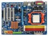
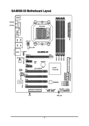
ATX GA-M56S-S3 Motherboard Layout KB_MS COAXIAL OPTICAL Socket AM2 COMA LPT 1394 USB ATX_12V LAN USB DDRII_1 DDRII_2 DDRII_3 DDRII_4 CPU_FAN AUDIO F_AUDIO PCIE_16 RTL8211BL PCIE_1 SPDIF_O PCIE_2 GA-M56S-S3 BIOS BATTERY CODEC PCI1 CLR_CMOS PCI2 nVIDIA® nForce 560 SATAII2SATAII3 CD_IN SPDIF_I PCI3 IT8716 PCI4 CI TSB43AB23 F_USB2 F_USB1 F_USB3 F1_1394 F2_1394 SYS_FAN F_PANEL FDD PWR_LED IDE SATAII0 SATAII1 - 7 -
ATX GA-M56S-S3 Motherboard Layout KB_MS COAXIAL OPTICAL Socket AM2 COMA LPT 1394 USB ATX_12V LAN USB DDRII_1 DDRII_2 DDRII_3 DDRII_4 CPU_FAN AUDIO F_AUDIO PCIE_16 RTL8211BL PCIE_1 SPDIF_O PCIE_2 GA-M56S-S3 BIOS BATTERY CODEC PCI1 CLR_CMOS PCI2 nVIDIA® nForce 560 SATAII2SATAII3 CD_IN SPDIF_I PCI3 IT8716 PCI4 CI TSB43AB23 F_USB2 F_USB1 F_USB3 F1_1394 F2_1394 SYS_FAN F_PANEL FDD PWR_LED IDE SATAII0 SATAII1 - 7 -

Manual
Page 9
...8226; Do not place the computer system on an uneven surface. • Do not place the computer system in contact with the motherboard circuit or its components. • Make sure there are uncertain about any metal leads or connectors. • It is best ...please verify that all cables and power connectors of electrostatic discharge (ESD). Hardware Installation English Chapter 1 Hardware Installation 1-1 Installation Precautions The motherboard contains numerous delicate electronic circuits and components which can lead to damage to system components as well as physical harm to the user....
...8226; Do not place the computer system on an uneven surface. • Do not place the computer system in contact with the motherboard circuit or its components. • Make sure there are uncertain about any metal leads or connectors. • It is best ...please verify that all cables and power connectors of electrostatic discharge (ESD). Hardware Installation English Chapter 1 Hardware Installation 1-1 Installation Precautions The motherboard contains numerous delicate electronic circuits and components which can lead to damage to system components as well as physical harm to the user....

Manual
Page 10
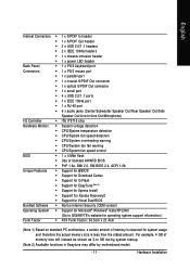
...138; 1 x CD In connector GA-M56S-S3 Motherboard - 10 - English 1-2 Product Specifications CPU Š Support for Socket AM2 processors: AMD AthlonTM 64 FX processor/AMD AthlonTM 64 X2 Dual-Core processor/ AMD AthlonTM 64 processor/AMD SempronTM processor (Go to GIGABYTE's website for the latest CPU support...system memory (Note 1) Š Dual channel memory architecture Š Support for DDR2 800/667/533 MHz memory modules (Go to GIGABYTE's website for the latest memory support list.) Audio Š Realtek ALC888 codec Š High Definition Audio Š 2/4/5.1/7.1-channel Š...
...138; 1 x CD In connector GA-M56S-S3 Motherboard - 10 - English 1-2 Product Specifications CPU Š Support for Socket AM2 processors: AMD AthlonTM 64 FX processor/AMD AthlonTM 64 X2 Dual-Core processor/ AMD AthlonTM 64 processor/AMD SempronTM processor (Go to GIGABYTE's website for the latest CPU support...system memory (Note 1) Š Dual channel memory architecture Š Support for DDR2 800/667/533 MHz memory modules (Go to GIGABYTE's website for the latest memory support list.) Audio Š Realtek ALC888 codec Š High Definition Audio Š 2/4/5.1/7.1-channel Š...
Manual
Page 11
...Dual BIOS Bundled Software Š Norton Internet Security (OEM version) Operating System Š Support for Microsoft® Windows® Vista/XP/2000 (Go to GIGABYTE's website for system usage and therefore the actual memory size is reserved for operating system support information.) Form Factor Š ATX Form Factor; 30.5cm..., a certain amount of memory size will instead be shown as 3.xx GB during system startup. (Note 2) Available functions in Easytune may differ by motherboard model. - 11 - Hardware Installation For example, 4 GB of memory is less than the stated amount.
...Dual BIOS Bundled Software Š Norton Internet Security (OEM version) Operating System Š Support for Microsoft® Windows® Vista/XP/2000 (Go to GIGABYTE's website for system usage and therefore the actual memory size is reserved for operating system support information.) Form Factor Š ATX Form Factor; 30.5cm..., a certain amount of memory size will instead be shown as 3.xx GB during system startup. (Note 2) Available functions in Easytune may differ by motherboard model. - 11 - Hardware Installation For example, 4 GB of memory is less than the stated amount.

Manual
Page 12
.... • Apply an even and thin layer of thermal grease on the computer if the CPU cooler is not recom- mended that the motherboard supports the CPU. (Go to GIGABYTE's website for the peripherals. A Small Triangle Mark Denotes Pin One of the CPU. • Do not turn off the computer and unplug... latest CPU support list.) • Always turn on the surface of the Socket AM2 CPU Socket A Small Triangle Marking Denotes CPU Pin One AM2 CPU GA-M56S-S3 Motherboard - 12 -
.... • Apply an even and thin layer of thermal grease on the computer if the CPU cooler is not recom- mended that the motherboard supports the CPU. (Go to GIGABYTE's website for the peripherals. A Small Triangle Mark Denotes Pin One of the CPU. • Do not turn off the computer and unplug... latest CPU support list.) • Always turn on the surface of the Socket AM2 CPU Socket A Small Triangle Marking Denotes CPU Pin One AM2 CPU GA-M56S-S3 Motherboard - 12 -

Manual
Page 13
... position. English B. CPU Socket Locking Lever Step 1: Completely lift up the CPU socket locking lever. Make sure that the CPU pins fit perfectly into the motherboard CPU socket. Do not force the CPU into the socket. Adjust the CPU orientation if this occurs. - 13 - Step 2: Align the CPU pin one finger...
... position. English B. CPU Socket Locking Lever Step 1: Completely lift up the CPU socket locking lever. Make sure that the CPU pins fit perfectly into the motherboard CPU socket. Do not force the CPU into the socket. Adjust the CPU orientation if this occurs. - 13 - Step 2: Align the CPU pin one finger...

Manual
Page 14
English 1-3-2 Installing the CPU Cooler Follow the steps below to correctly install the CPU cooler on the CPU. (The following procedure uses the GIGABYTE cooler as the picture above shows) to lock into place. (Refer to your CPU cooler installation manual for instructions on installing the cooler.) Step ... the CPU. Use extreme care when removing the CPU cooler because the thermal grease/tape between the CPU cooler and CPU may damage the CPU. GA-M56S-S3 Motherboard - 14 - Step 4: Turn the cam handle from the left side to the right side (as the example.) Step 1: Apply an even and thin...
English 1-3-2 Installing the CPU Cooler Follow the steps below to correctly install the CPU cooler on the CPU. (The following procedure uses the GIGABYTE cooler as the picture above shows) to lock into place. (Refer to your CPU cooler installation manual for instructions on installing the cooler.) Step ... the CPU. Use extreme care when removing the CPU cooler because the thermal grease/tape between the CPU cooler and CPU may damage the CPU. GA-M56S-S3 Motherboard - 14 - Step 4: Turn the cam handle from the left side to the right side (as the example.) Step 1: Apply an even and thin...
Manual
Page 15
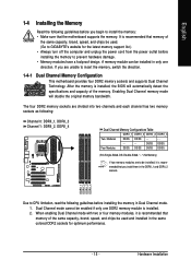
..., read the following guidelines before you begin to GIGABYTE's website for optimum performance. - 15 - When enabling Dual Channel mode with two or four memory modules, it is installed. 2. It is recommended that the motherboard supports the memory. If you install them in ...from the power outlet before installing the memory to insert the memory, switch the direction. 1-4-1 Dual Channel Memory Configuration This motherboard provides four DDR2 memory sockets and supports Dual Channel Technology. Enabling Dual Channel memory mode will automatically detect the specifications and...
..., read the following guidelines before you begin to GIGABYTE's website for optimum performance. - 15 - When enabling Dual Channel mode with two or four memory modules, it is installed. 2. It is recommended that the motherboard supports the memory. If you install them in ...from the power outlet before installing the memory to insert the memory, switch the direction. 1-4-1 Dual Channel Memory Configuration This motherboard provides four DDR2 memory sockets and supports Dual Channel Technology. Enabling Dual Channel memory mode will automatically detect the specifications and...
Manual
Page 16
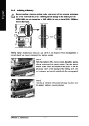
... both ends of the socket will snap into the memory socket. Follow the steps below to the memory module. Place the memory module on this motherboard. Notch DDR2 DIMM A DDR2 memory module has a notch, so it vertically into place when the memory module is securely inserted. Step 2: The clips at both... it can only fit in the memory sockets. DDR2 DIMMs are not compatible to DDR DIMMs. Be sure to install DDR2 DIMMs on the socket. GA-M56S-S3 Motherboard - 16 -
... both ends of the socket will snap into the memory socket. Follow the steps below to the memory module. Place the memory module on this motherboard. Notch DDR2 DIMM A DDR2 memory module has a notch, so it vertically into place when the memory module is securely inserted. Step 2: The clips at both... it can only fit in the memory sockets. DDR2 DIMMs are not compatible to DDR DIMMs. Be sure to install DDR2 DIMMs on the socket. GA-M56S-S3 Motherboard - 16 -

Manual
Page 17
... your computer. English 1-5 Installing an Expansion Card Read the following guidelines before installing an expansion card to install an expansion card: • Make sure the motherboard supports the expansion card. Make sure the metal contacts on your expansion card in the expansion slot. 1.
... your computer. English 1-5 Installing an Expansion Card Read the following guidelines before installing an expansion card to install an expansion card: • Make sure the motherboard supports the expansion card. Make sure the metal contacts on your expansion card in the expansion slot. 1.
Manual
Page 18
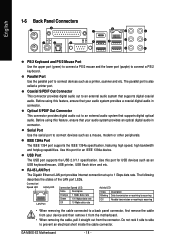
...rate Activity LED: State Description Blinking Data transmission or receiving is occurring Off No data transmission or receiving is also called a printer port. GA-M56S-S3 Motherboard - 18 - USB Port The USB port supports the USB 2.0/1.1 specification. Before using this feature, ensure that your audio system provides a...USB printer, USB flash drive and etc. Use this port for an IEEE 1394a device. Do not rock it straight out from the motherboard. • When removing the cable, pull it side to side to connect devices such as a mouse, modem or other peripherals....
...rate Activity LED: State Description Blinking Data transmission or receiving is occurring Off No data transmission or receiving is also called a printer port. GA-M56S-S3 Motherboard - 18 - USB Port The USB port supports the USB 2.0/1.1 specification. Before using this feature, ensure that your audio system provides a...USB printer, USB flash drive and etc. Use this port for an IEEE 1394a device. Do not rock it straight out from the motherboard. • When removing the cable, pull it side to side to connect devices such as a mouse, modem or other peripherals....

Manual
Page 20
GA-M56S-S3 Motherboard - 20 - English 1-7 Internal Connectors 31 2 11 14 9 18 6 12 7 13 15 17 5 16 8 4 10 1) ATX_12V 2) ATX 3) CPU_FAN 4) SYS_FAN 5) FDD 6) IDE 7) SATAII0 / 1 / 2 / 3 8) PWR_LED 9) BATTERY 10) F_PANEL ..., make sure your devices are compliant with the connectors you wish to connect. • Before installing the devices, be sure to the connector on the motherboard. Unplug the power cord from the power outlet to prevent damage to the devices. • After installing the device and before connecting external devices: •...
GA-M56S-S3 Motherboard - 20 - English 1-7 Internal Connectors 31 2 11 14 9 18 6 12 7 13 15 17 5 16 8 4 10 1) ATX_12V 2) ATX 3) CPU_FAN 4) SYS_FAN 5) FDD 6) IDE 7) SATAII0 / 1 / 2 / 3 8) PWR_LED 9) BATTERY 10) F_PANEL ..., make sure your devices are compliant with the connectors you wish to connect. • Before installing the devices, be sure to the connector on the motherboard. Unplug the power cord from the power outlet to prevent damage to the devices. • After installing the device and before connecting external devices: •...

Manual
Page 21
... power supply cable into pins under the protective cover when using a 2x12 power supply, remove the protective cover from the main power connector on the motherboard. The power connector possesses a foolproof design. English 1/2) ATX_12V/ATX (2x2 12V Power Connector and 2x12 Main Power Connector) With the use of the power connector... all devices are properly installed. Before connecting the power connector, first make sure the power supply is turned off and all the components on the motherboard.
... power supply cable into pins under the protective cover when using a 2x12 power supply, remove the protective cover from the main power connector on the motherboard. The power connector possesses a foolproof design. English 1/2) ATX_12V/ATX (2x2 12V Power Connector and 2x12 Main Power Connector) With the use of the power connector... all devices are properly installed. Before connecting the power connector, first make sure the power supply is turned off and all the components on the motherboard.

Manual
Page 22
...A red power connector wire indicates a positive connection and requires a +12V voltage. Do not place a jumper cap on the connector. 33 1 34 2 GA-M56S-S3 Motherboard - 22 - The types of a CPU/system fan with color-coded power connector wires. Each fan header supplies a +12V power voltage and possesses a... foolproof insertion design. For optimum heat dissipation, it in damage to connect it is the ground wire. The motherboard supports CPU/system fan speed control, which requires the use of floppy disk drives supported are designed with fan speed control design.
...A red power connector wire indicates a positive connection and requires a +12V voltage. Do not place a jumper cap on the connector. 33 1 34 2 GA-M56S-S3 Motherboard - 22 - The types of a CPU/system fan with color-coded power connector wires. Each fan header supplies a +12V power voltage and possesses a... foolproof insertion design. For optimum heat dissipation, it in damage to connect it is the ground wire. The motherboard supports CPU/system fan speed control, which requires the use of floppy disk drives supported are designed with fan speed control design.
Manual
Page 24
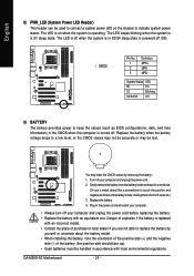
...power cord and restart your computer. • Always turn off when the system is operating. Danger of the battery holder, making them short for one . GA-M56S-S3 Motherboard - 24 - Replace the battery. 4. English 8) PWR_LED (System Power LED Header) This header can be used to connect a system power LED on ...1. The LED keeps blinking when the system is turned off (S5). Definition 1 MPD+ 1 2 MPD- 3 MPD- System Status LED S0 On S1 Blinking S3/S4/S5 Off 9) BATTERY The battery provides power to a low level, or the CMOS values may not be accurate or may clear the CMOS values...
...power cord and restart your computer. • Always turn off when the system is operating. Danger of the battery holder, making them short for one . GA-M56S-S3 Motherboard - 24 - Replace the battery. 4. English 8) PWR_LED (System Power LED Header) This header can be used to connect a system power LED on ...1. The LED keeps blinking when the system is turned off (S5). Definition 1 MPD+ 1 2 MPD- 3 MPD- System Status LED S0 On S1 Blinking S3/S4/S5 Off 9) BATTERY The battery provides power to a low level, or the CMOS values may not be accurate or may clear the CMOS values...


