Manual
Page 1
GA-M55S-S3 (rev. 2.0) AMD Socket AM2 Processor Motherboard User's Manual Rev. 2002 12ME-M55S3R-2002R * The WEEE marking on the product indicates this product must not be disposed of with user's other household waste and must be handed over to a designated collection point for the recycling of waste electrical and electronic equipment!! * The WEEE marking applies only in European Union's member states.
GA-M55S-S3 (rev. 2.0) AMD Socket AM2 Processor Motherboard User's Manual Rev. 2002 12ME-M55S3R-2002R * The WEEE marking on the product indicates this product must not be disposed of with user's other household waste and must be handed over to a designated collection point for the recycling of waste electrical and electronic equipment!! * The WEEE marking applies only in European Union's member states.
Manual
Page 2
Motherboard GA-M55S-S3 (rev. 2.0) Nov. 10, 2006 Motherboard GA-M55S-S3 (rev. 2.0) Nov. 10, 2006
Motherboard GA-M55S-S3 (rev. 2.0) Nov. 10, 2006 Motherboard GA-M55S-S3 (rev. 2.0) Nov. 10, 2006
Manual
Page 4
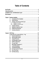
Table of Contents ItemChecklist ...6 OptionalAccessories ...6 GA-M55S-S3 (rev. 2.0) Motherboard Layout 7 Block Diagram ...8 Chapter 1 Hardware Installation 9 1-1 Considerations Prior to Installation 9 1-2 Feature Summary 10 1-3 Installation of the CPU and CPU Cooler 12 1-3-1 Installation of the ...
Table of Contents ItemChecklist ...6 OptionalAccessories ...6 GA-M55S-S3 (rev. 2.0) Motherboard Layout 7 Block Diagram ...8 Chapter 1 Hardware Installation 9 1-1 Considerations Prior to Installation 9 1-2 Feature Summary 10 1-3 Installation of the CPU and CPU Cooler 12 1-3-1 Installation of the ...
Manual
Page 7
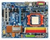
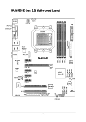
GA-M55S-S3 (rev. 2.0) Motherboard Layout CPU_FAN KB_MS ATX_12V ATX SPDIF_O SPDIFO_OPT Socket AM2 COMA LPT PWR_FAN USB 1394 USB LAN1 Marvell 88E1116 AUDIO PCIE_12V F_AUDIO PCIE_1 CODEC PCIE_16_1 PCIE_2 SPDIF_I CD_IN PCIE_3 PCIE_4 PCI1 IT8716 PCI2 REV: 2.0 FDD DDRII_1 DDRII_2 DDRII_3 DDRII_4 GA-M55S-S3 IDE1 SATAII4 SATAII1 SATAII2 SATAII3 BIOS nVIDIA® nForce 550 CLR_CMOS TSB43AB23 BATTERY F_USB3 F_USB2 F_USB1 F1_1394 F2_1394 CI F_PANEL PWR_LED SYS_FAN - 7 -
GA-M55S-S3 (rev. 2.0) Motherboard Layout CPU_FAN KB_MS ATX_12V ATX SPDIF_O SPDIFO_OPT Socket AM2 COMA LPT PWR_FAN USB 1394 USB LAN1 Marvell 88E1116 AUDIO PCIE_12V F_AUDIO PCIE_1 CODEC PCIE_16_1 PCIE_2 SPDIF_I CD_IN PCIE_3 PCIE_4 PCI1 IT8716 PCI2 REV: 2.0 FDD DDRII_1 DDRII_2 DDRII_3 DDRII_4 GA-M55S-S3 IDE1 SATAII4 SATAII1 SATAII2 SATAII3 BIOS nVIDIA® nForce 550 CLR_CMOS TSB43AB23 BATTERY F_USB3 F_USB2 F_USB1 F1_1394 F2_1394 CI F_PANEL PWR_LED SYS_FAN - 7 -
Manual
Page 10
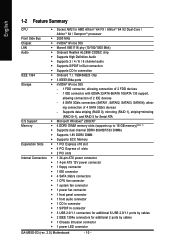
... (SATAII1, SATAII2, SATAII3, SATAII4), allow- English 1-2 Feature Summary CPU Š Socket AM2 for additional 2 ports by cables Š 1 Chassis Intrusion connector Š 1 power LED connector GA-M55S-S3 (rev. 2.0) Motherboard - 10 - Supports data striping (RAID 0), mirroring (RAID 1), striping+mirroring (RAID 0+1), and RAID 5 for Serial ATA O.S Support Š Microsoft Windows® 2000/XP Memory Š...
... (SATAII1, SATAII2, SATAII3, SATAII4), allow- English 1-2 Feature Summary CPU Š Socket AM2 for additional 2 ports by cables Š 1 Chassis Intrusion connector Š 1 power LED connector GA-M55S-S3 (rev. 2.0) Motherboard - 10 - Supports data striping (RAID 0), mirroring (RAID 1), striping+mirroring (RAID 0+1), and RAID 5 for Serial ATA O.S Support Š Microsoft Windows® 2000/XP Memory Š...
Manual
Page 12
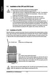
... including the CPU, graphics card, memory, hard drive, etc. 1-3-1 Installation of heat paste between the CPU and CPU cooler. 4. The CPU will not insert properly. GA-M55S-S3 (rev. 2.0) Motherboard - 12 - If you wish to inserting the CPU. Please set the CPU host frequency in Fig. 1 (90o to the unlocked position as shown in...
... including the CPU, graphics card, memory, hard drive, etc. 1-3-1 Installation of heat paste between the CPU and CPU cooler. 4. The CPU will not insert properly. GA-M55S-S3 (rev. 2.0) Motherboard - 12 - If you wish to inserting the CPU. Please set the CPU host frequency in Fig. 1 (90o to the unlocked position as shown in...

Manual
Page 14
... brand be used can be installed in one direction. Please make sure that the memory used is supported by the motherboard. Then push it down. GA-M55S-S3 (rev. 2.0) Motherboard - 14 - A memory module can only fit in one direction. Fig.2 Close the plastic clip at both edges of Memory Before installing the memory modules...
... brand be used can be installed in one direction. Please make sure that the memory used is supported by the motherboard. Then push it down. GA-M55S-S3 (rev. 2.0) Motherboard - 14 - A memory module can only fit in one direction. Fig.2 Close the plastic clip at both edges of Memory Before installing the memory modules...
Manual
Page 16
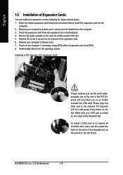
... to the onboard PCI Express x16 slot and press firmly down on the slot. To install a VGA card or to install/ uninstall the VGA card. GA-M55S-S3 (rev. 2.0) Motherboard - 16 - Installing a PCI Express x16 expansion card: Please carefully pull out the small whitedrawable bar at the end of the expansion card. 6. Remove your...
... to the onboard PCI Express x16 slot and press firmly down on the slot. To install a VGA card or to install/ uninstall the VGA card. GA-M55S-S3 (rev. 2.0) Motherboard - 16 - Installing a PCI Express x16 expansion card: Please carefully pull out the small whitedrawable bar at the end of the expansion card. 6. Remove your...
Manual
Page 18
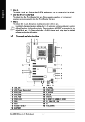
... steps for detailed software configuration information. 1-7 Connectors Introduction 3 14 6 2 8 13 15 14 7 1) ATX_12V 2) ATX (Power Connector) 3) PCIE_12V 4) CPU_FAN 5) SYS_FAN 6) PWR_FAN 7) FDD 8) IDE1 9) SATAII1 / 2 / 3 / 4 10) BATTERY GA-M55S-S3 (rev. 2.0) Motherboard 9 9 19 10 5 17 1812 11 16 11) F_PANEL 12) PWR_LED 13) F_AUDIO 14) CD_IN 15) SPDIF_I 16) F_USB1 / F_USB2 / F_USB3 17) F1_1394 / F2_1394 18...
... steps for detailed software configuration information. 1-7 Connectors Introduction 3 14 6 2 8 13 15 14 7 1) ATX_12V 2) ATX (Power Connector) 3) PCIE_12V 4) CPU_FAN 5) SYS_FAN 6) PWR_FAN 7) FDD 8) IDE1 9) SATAII1 / 2 / 3 / 4 10) BATTERY GA-M55S-S3 (rev. 2.0) Motherboard 9 9 19 10 5 17 1812 11 16 11) F_PANEL 12) PWR_LED 13) F_AUDIO 14) CD_IN 15) SPDIF_I 16) F_USB1 / F_USB2 / F_USB3 17) F1_1394 / F2_1394 18...
Manual
Page 20
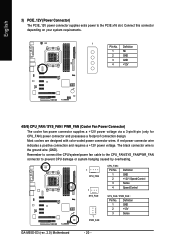
... wires. Remember to connect the CPU/system/power fan cable to the CPU_FAN/SYS_FAN/PWR_FAN connector to the PCIE x16 slot. Definition 1 GND 2 +12V 3 Sense GA-M55S-S3 (rev. 2.0) Motherboard - 20 - A red power connector wire indicates a positive connection and requires a +12V power voltage. Connect this connector depending on your system requirements. 1 PIin No. The...
... wires. Remember to connect the CPU/system/power fan cable to the CPU_FAN/SYS_FAN/PWR_FAN connector to the PCIE x16 slot. Definition 1 GND 2 +12V 3 Sense GA-M55S-S3 (rev. 2.0) Motherboard - 20 - A red power connector wire indicates a positive connection and requires a +12V power voltage. Connect this connector depending on your system requirements. 1 PIin No. The...
Manual
Page 22
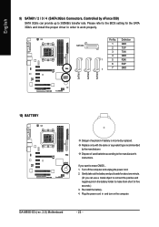
... proper driver in and turn on the computer. Please refer to the BIOS setting for about one minute. (Or you want to the manufacturer's instructions. GA-M55S-S3 (rev. 2.0) Motherboard - 22 - Definition 1 GND 2 TXP 3 TXN 4 GND 1 5 RXN 6 RXP 7 7 GND 10) BATTERY Danger of used batteries according to erase CMOS...
... proper driver in and turn on the computer. Please refer to the BIOS setting for about one minute. (Or you want to the manufacturer's instructions. GA-M55S-S3 (rev. 2.0) Motherboard - 22 - Definition 1 GND 2 TXP 3 TXN 4 GND 1 5 RXN 6 RXP 7 7 GND 10) BATTERY Danger of used batteries according to erase CMOS...
Manual
Page 24
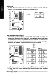
... between the module and connector will blink when the system enters suspend mode(S1). To connect an AC97 front panel audio module to this connector. GA-M55S-S3 (rev. 2.0) Motherboard - 24 - It will make the audio device unable to work or even damage it. English 12) PWR_LED The PWR_LED connector is connected with the...
... between the module and connector will blink when the system enters suspend mode(S1). To connect an AC97 front panel audio module to this connector. GA-M55S-S3 (rev. 2.0) Motherboard - 24 - It will make the audio device unable to work or even damage it. English 12) PWR_LED The PWR_LED connector is connected with the...
Manual
Page 26
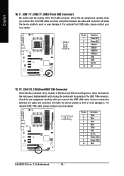
... has features like high speed, highbandwidth and hot plug. Definition 2 10 1 9 1 TPA+ 2 TPA- 3 GND 4 GND 5 TPB+ 6 TPB- 7 No Pin 7 Power (12V) 8 Power (12V) 10 GND GA-M55S-S3 (rev. 2.0) Motherboard - 26 - Pin No. English 16) F_ USB1 / F_USB2 / F_USB3 (Front USB Connector) Be careful with the polarity of the IEEE 1394 connector. Be careful...
... has features like high speed, highbandwidth and hot plug. Definition 2 10 1 9 1 TPA+ 2 TPA- 3 GND 4 GND 5 TPB+ 6 TPB- 7 No Pin 7 Power (12V) 8 Power (12V) 10 GND GA-M55S-S3 (rev. 2.0) Motherboard - 26 - Pin No. English 16) F_ USB1 / F_USB2 / F_USB3 (Front USB Connector) Be careful with the polarity of the IEEE 1394 connector. Be careful...
Manual
Page 28
English GA-M55S-S3 (rev. 2.0) Motherboard - 28 -
English GA-M55S-S3 (rev. 2.0) Motherboard - 28 -
Manual
Page 30
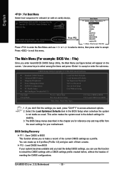
... select a device, then press enter to reload the CMOS settings with a CMOS settings profile created before, without the hassles of resetting the CMOS configurations. GA-M55S-S3 (rev. 2.0) Motherboard - 30 - M55S-S3 FAa . . . . :BIOS Setup/Q-Flash, : XpressRecovery2, : Boot Menu 09/28/2006-NV-MCP55S-6A61JG07C-00 Press F12 Boot Menu == Select a Boot First device == Floppy LS120...
... select a device, then press enter to reload the CMOS settings with a CMOS settings profile created before, without the hassles of resetting the CMOS configurations. GA-M55S-S3 (rev. 2.0) Motherboard - 30 - M55S-S3 FAa . . . . :BIOS Setup/Q-Flash, : XpressRecovery2, : Boot Menu 09/28/2006-NV-MCP55S-6A61JG07C-00 Press F12 Boot Menu == Select a Boot First device == Floppy LS120...

Manual
Page 32
... of three methods: Auto Allows BIOS to automatically detect IDE/SATA devices during POST(default) None Select this option for the hard drive. For example, 1 p.m. GA-M55S-S3 (rev. 2.0) Motherboard - 32 - IDE Channel 0 Master/Slave devices setup. Access Mode Use this to select this if no IDE/SATA devices are used and the system...
... of three methods: Auto Allows BIOS to automatically detect IDE/SATA devices during POST(default) None Select this option for the hard drive. For example, 1 p.m. GA-M55S-S3 (rev. 2.0) Motherboard - 32 - IDE Channel 0 Master/Slave devices setup. Access Mode Use this to select this if no IDE/SATA devices are used and the system...

Manual
Page 34
... priority by USB-CDROM. Enabled BIOS searches for floppy disk drive to determine it down the list. Press to move it is 360K. (Default value) GA-M55S-S3 (rev. 2.0) Motherboard - 34 - USB-FDD USB-ZIP Select your boot device priority by USB-FDD. Disabled Disable this menu. Disabled BIOS will determine the floppy disk...
... priority by USB-CDROM. Enabled BIOS searches for floppy disk drive to determine it down the list. Press to move it is 360K. (Default value) GA-M55S-S3 (rev. 2.0) Motherboard - 34 - USB-FDD USB-ZIP Select your boot device priority by USB-FDD. Disabled Disable this menu. Disabled BIOS will determine the floppy disk...

Manual
Page 36
... 1 Secondary RAID Enabled Enable RAID function for the first channel of the first SATA controller. (Default value) Disabled Disable the RAID function of this channel. GA-M55S-S3 (rev. 2.0) Motherboard - 36 - English 2-3 Integrated Peripherals CMOS Setup Utility-Copyright (C) 1984-2006 Award Software Integrated Peripherals Serial-ATA RAID Config On-Chip IDE Channel0 On-Chip...
... 1 Secondary RAID Enabled Enable RAID function for the first channel of the first SATA controller. (Default value) Disabled Disable the RAID function of this channel. GA-M55S-S3 (rev. 2.0) Motherboard - 36 - English 2-3 Integrated Peripherals CMOS Setup Utility-Copyright (C) 1984-2006 Award Software Integrated Peripherals Serial-ATA RAID Config On-Chip IDE Channel0 On-Chip...

Manual
Page 38
... Parallel port as shown in a 10/100 Mbps environment, their Status fields will show Open and the Length fields show 0.0m. When a Cable Problem Occurs... GA-M55S-S3 (rev. 2.0) Motherboard - 38 - Onboard 1394 Enabled Enable onboard IEEE 1394 function. (Default value) Disabled Disable onboard IEEE 1394 function.
... Parallel port as shown in a 10/100 Mbps environment, their Status fields will show Open and the Length fields show 0.0m. When a Cable Problem Occurs... GA-M55S-S3 (rev. 2.0) Motherboard - 38 - Onboard 1394 Enabled Enable onboard IEEE 1394 function. (Default value) Disabled Disable onboard IEEE 1394 function.

Manual
Page 40
...: General Help F7: Optimized Defaults ACPI Suspend Type S1(POS) Set ACPI suspend type to S1/POS(Power On Suspend). (Default value) S3(STR) Set ACPI suspend type to S3/STR(Suspend To RAM). USB Resume from Suspend Disabled Enabled Disable this function. (Default value) Enable alarm function to POWER ON system... An incoming call via modem can set "Power-On by Alarm x Day of Month Alarm : Everyday, 1~31 Time (hh: mm: ss) Alarm : (0~23) : (0~59) : (0~59) GA-M55S-S3 (rev. 2.0) Motherboard - 40 -
...: General Help F7: Optimized Defaults ACPI Suspend Type S1(POS) Set ACPI suspend type to S1/POS(Power On Suspend). (Default value) S3(STR) Set ACPI suspend type to S3/STR(Suspend To RAM). USB Resume from Suspend Disabled Enabled Disable this function. (Default value) Enable alarm function to POWER ON system... An incoming call via modem can set "Power-On by Alarm x Day of Month Alarm : Everyday, 1~31 Time (hh: mm: ss) Alarm : (0~23) : (0~59) : (0~59) GA-M55S-S3 (rev. 2.0) Motherboard - 40 -


