
User Manual
Page 1
GA-K8N51PVM9-RH-NV AMD Socket 939 Processor Motherboard User's Manual Rev. 1004 12ME-N51PVM9R-1004R * The WEEE marking on the product indicates this product must not be disposed of with user's other household waste and must be handed over to a designated collection point for the recycling of waste electrical and electronic equipment!! * The WEEE marking applies only in European Union's member states.
GA-K8N51PVM9-RH-NV AMD Socket 939 Processor Motherboard User's Manual Rev. 1004 12ME-N51PVM9R-1004R * The WEEE marking on the product indicates this product must not be disposed of with user's other household waste and must be handed over to a designated collection point for the recycling of waste electrical and electronic equipment!! * The WEEE marking applies only in European Union's member states.

User Manual
Page 4
Table of Contents ItemChecklist ...6 OptionalAccessories ...6 GA-K8N51PVM9-RH-NV Motherboard Layout 7 Block Diagram ...8 Chapter 1 Hardware Installation 9 1-1 Considerations Prior to Installation 9 1-2 Feature Summary 10 1-3 Installation of the CPU and CPU Cooler 12 1-3-1 Installation of the CPU ...
Table of Contents ItemChecklist ...6 OptionalAccessories ...6 GA-K8N51PVM9-RH-NV Motherboard Layout 7 Block Diagram ...8 Chapter 1 Hardware Installation 9 1-1 Considerations Prior to Installation 9 1-2 Feature Summary 10 1-3 Installation of the CPU and CPU Cooler 12 1-3-1 Installation of the CPU ...

User Manual
Page 9
...about any installation steps or have these items on the motherboard or within a electrostatic shielding container. 5. To prevent damage to the motherboard, please do not allow screws to come in the user manual. 3. Damage due to be an unofficial Gigabyte product. - 9 - Damage as a result of ...violating the conditions recommended in contact with the motherboard circuit or its power cord. 2. Prior to the installation of an antistatic pad or within ...
...about any installation steps or have these items on the motherboard or within a electrostatic shielding container. 5. To prevent damage to the motherboard, please do not allow screws to come in the user manual. 3. Damage due to be an unofficial Gigabyte product. - 9 - Damage as a result of ...violating the conditions recommended in contact with the motherboard circuit or its power cord. 2. Prior to the installation of an antistatic pad or within ...

User Manual
Page 10
English 1-2 Feature Summary CPU Š Supports Socket 939 for additional 4 ports by cables Š 1 TPM_CLR connector Š 1 PWR_LED connector Š 1 CI connector GA-K8N51PVM9-RH-NV Motherboard - 10 - Supports data striping (RAID 0), mirroring (RAID 1) for Serial ATA O.S Support Š Microsoft Windows 2000/XP Memory Š 4 DDR DIMM memory slots (supports up to 4 ...
English 1-2 Feature Summary CPU Š Supports Socket 939 for additional 4 ports by cables Š 1 TPM_CLR connector Š 1 PWR_LED connector Š 1 CI connector GA-K8N51PVM9-RH-NV Motherboard - 10 - Supports data striping (RAID 0), mirroring (RAID 1) for Serial ATA O.S Support Š Microsoft Windows 2000/XP Memory Š 4 DDR DIMM memory slots (supports up to 4 ...

User Manual
Page 11
... actual memory size is supported will depend on the CPU you have to connect the front panel audio module to the F_AUDIO connector on different motherboards. - 11 - Hardware Installation Then set the type of equipment from the audio software. English Rear Panel I/O Š 1 PS/2 keyboard port Š 1 PS/2 mouse port Š... Š Micro ATX form factor; 24.4cm x 24.4cm (Note 1) To achieve 8-Channel Audio output, you install. (Note 4) EasyTune functions may vary depending on the motherboard.
... actual memory size is supported will depend on the CPU you have to connect the front panel audio module to the F_AUDIO connector on different motherboards. - 11 - Hardware Installation Then set the type of equipment from the audio software. English Rear Panel I/O Š 1 PS/2 keyboard port Š 1 PS/2 mouse port Š... Š Micro ATX form factor; 24.4cm x 24.4cm (Note 1) To achieve 8-Channel Audio output, you install. (Note 4) EasyTune functions may vary depending on the motherboard.

User Manual
Page 12
...specifications. Please make sure that the CPU pins fit perfectly into its original position. Once the CPU is not recommended that none are bent. GA-K8N51PVM9-RH-NV Motherboard - 12 - If you wish to set the CPU host frequency in Fig. 2. Please set the frequency beyond hardware specifications since it ...place. If you install the CPU in Fig. 1 (90o to inserting the CPU. Do not force the CPU into position making sure that the motherboard supports the CPU. 2. Fig.2 Pin 1 location on the socket as shown in the wrong direction, the CPU will not fit if positioned incorrectly...
...specifications. Please make sure that the CPU pins fit perfectly into its original position. Once the CPU is not recommended that none are bent. GA-K8N51PVM9-RH-NV Motherboard - 12 - If you wish to set the CPU host frequency in Fig. 2. Please set the frequency beyond hardware specifications since it ...place. If you install the CPU in Fig. 1 (90o to inserting the CPU. Do not force the CPU into position making sure that the motherboard supports the CPU. 2. Fig.2 Pin 1 location on the socket as shown in the wrong direction, the CPU will not fit if positioned incorrectly...

User Manual
Page 13
... heat paste. English 1-3-2 Installation of the CPU Cooler Fig.1 Before installing the CPU cooler, please first add an even layer of heat paste on the motherboard so that either thermal tape rather than heat paste be used for detailed installation instructions).
... heat paste. English 1-3-2 Installation of the CPU Cooler Fig.1 Before installing the CPU cooler, please first add an even layer of heat paste on the motherboard so that either thermal tape rather than heat paste be used for detailed installation instructions).

User Manual
Page 14
Please make sure that the computer power is switched off to prevent hardware damage. 3. The motherboard supports DDR memory modules, whereby BIOS will automatically detect memory capacity and specifications. The memory capacity used . 2. Insert the DIMM memory module vertically into ... push it down. A memory module can differ with the following conditions: 1. If you wish to remove the DIMM module. GA-K8N51PVM9-RH-NV Motherboard - 14 - Notch DDR Fig.1 The DIMM socket has a notch, so the DIMM memory module can be installed in one direction. Memory modules have a foolproof ...
Please make sure that the computer power is switched off to prevent hardware damage. 3. The motherboard supports DDR memory modules, whereby BIOS will automatically detect memory capacity and specifications. The memory capacity used . 2. Insert the DIMM memory module vertically into ... push it down. A memory module can differ with the following conditions: 1. If you wish to remove the DIMM module. GA-K8N51PVM9-RH-NV Motherboard - 14 - Notch DDR Fig.1 The DIMM socket has a notch, so the DIMM memory module can be installed in one direction. Memory modules have a foolproof ...

User Manual
Page 16
... contacts on the slot. Install related driver from BIOS. 8. GA-K8N51PVM9-RH-NV Motherboard - 16 - Press the expansion card firmly into the computer. 2. Please align the VGA card to the onboard PCI Express x16 slot and press firmly down on the card are indeed seated in motherboard. 4. Make sure your computer's chassis cover, screws and...
... contacts on the slot. Install related driver from BIOS. 8. GA-K8N51PVM9-RH-NV Motherboard - 16 - Press the expansion card firmly into the computer. 2. Please align the VGA card to the onboard PCI Express x16 slot and press firmly down on the card are indeed seated in motherboard. 4. Make sure your computer's chassis cover, screws and...

User Manual
Page 18
English 1-7 Connectors Introduction 1 3 2 5 11 6 9 17 18 7 12 10 15 16 4 14 13 8 1) ATX_12V 2) ATX (Power Connector) 3) CPU_FAN 4) SYS_FAN 5) FDD 6) IDE1 / IDE2 7) SATAII0_1 / SATAII2_3 8) PWR_LED 9) BATTERY 10) F_PANEL 11) F_AUDIO 12) CD_IN 13) F_USB1 / F_USB2 14) TPM_CLR 15) SPDIF_IO 16) COMA 17) CLR_CMOS 18) CI GA-K8N51PVM9-RH-NV Motherboard - 18 -
English 1-7 Connectors Introduction 1 3 2 5 11 6 9 17 18 7 12 10 15 16 4 14 13 8 1) ATX_12V 2) ATX (Power Connector) 3) CPU_FAN 4) SYS_FAN 5) FDD 6) IDE1 / IDE2 7) SATAII0_1 / SATAII2_3 8) PWR_LED 9) BATTERY 10) F_PANEL 11) F_AUDIO 12) CD_IN 13) F_USB1 / F_USB2 14) TPM_CLR 15) SPDIF_IO 16) COMA 17) CLR_CMOS 18) CI GA-K8N51PVM9-RH-NV Motherboard - 18 -

User Manual
Page 19
Caution! If you use a 24-pin ATX power supply, please remove the small cover on the power connector on the motherboard and connect tightly. otherwise, please do not remove it. Definition 1 GND 3 4 2 GND 1 2 3 +12V 4 +12V 13 1 24 12 Pin No. 1 2 3 4 5 6 7 8 9 10 11 12 ...power, the result can lead to an unstable system or a system that is recommended that a power supply that all the components on the motherboard. Hardware Installation Before connecting the power connector, please make sure that can supply enough stable power to the CPU. Align the power connector ...
Caution! If you use a 24-pin ATX power supply, please remove the small cover on the power connector on the motherboard and connect tightly. otherwise, please do not remove it. Definition 1 GND 3 4 2 GND 1 2 3 +12V 4 +12V 13 1 24 12 Pin No. 1 2 3 4 5 6 7 8 9 10 11 12 ...power, the result can lead to an unstable system or a system that is recommended that a power supply that all the components on the motherboard. Hardware Installation Before connecting the power connector, please make sure that can supply enough stable power to the CPU. Align the power connector ...

User Manual
Page 20
... cable to the CPU_FAN/SYS_FAN connector to connect the FDD cable while the other end of the foolproof groove in the FDD connector. 34 33 2 1 GA-K8N51PVM9-RH-NV Motherboard - 20 - A red power connector wire indicates a positive connection and requires a +12V power voltage.
... cable to the CPU_FAN/SYS_FAN connector to connect the FDD cable while the other end of the foolproof groove in the FDD connector. 34 33 2 1 GA-K8N51PVM9-RH-NV Motherboard - 20 - A red power connector wire indicates a positive connection and requires a +12V power voltage.
User Manual
Page 22
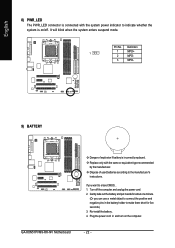
... indicate whether the system is on the computer. English 8) PWR_LED The PWR_LED connector is connected with the same or equivalent type recommended by the manufacturer. GA-K8N51PVM9-RH-NV Motherboard - 22 -
... indicate whether the system is on the computer. English 8) PWR_LED The PWR_LED connector is connected with the same or equivalent type recommended by the manufacturer. GA-K8N51PVM9-RH-NV Motherboard - 22 -

User Manual
Page 24
.... English 11) F_AUDIO (Front Audio Panel Connector) This connector supports either HD (High Definition) or AC97 front panel audio module. Definition 1 CD-L 2 GND 3 GND 4 CD-R GA-K8N51PVM9-RH-NV Motherboard - 24 -
.... English 11) F_AUDIO (Front Audio Panel Connector) This connector supports either HD (High Definition) or AC97 front panel audio module. Definition 1 CD-L 2 GND 3 GND 4 CD-R GA-K8N51PVM9-RH-NV Motherboard - 24 -

User Manual
Page 26
... connector. For optional SPDIF cable, please contact your nearest dealer for optional COMA cable. 2 10 1 9 Pin No. 1 2 3 4 5 6 7 8 9 10 Definition NDCDANSINA NSOUTA NDTRAGND NDSRANRTSANCTSANRIANo Pin GA-K8N51PVM9-RH-NV Motherboard - 26 - Use this feature only when your device has digital output function. Use SPDIF IN feature only when your stereo system has digital input function...
... connector. For optional SPDIF cable, please contact your nearest dealer for optional COMA cable. 2 10 1 9 Pin No. 1 2 3 4 5 6 7 8 9 10 Definition NDCDANSINA NSOUTA NDTRAGND NDSRANRTSANCTSANRIANo Pin GA-K8N51PVM9-RH-NV Motherboard - 26 - Use this feature only when your device has digital output function. Use SPDIF IN feature only when your stereo system has digital input function...

User Manual
Page 29
...SRAM. If you to quickly and easily update or backup BIOS without entering the operating system. @BIOS is displayed at the bottom of the motherboard. Q-Flash allows the user to the CMOS SETUP screen. When the power is turned off, the battery on , pressing the button during ...BIOS Setup BIOS (Basic Input and Output System) includes a CMOS SETUP utility which allows user to configure required settings or to a new BIOS, either Gigabyte's Q-Flash or @BIOS utility can enter the BIOS setup screen by pressing "Ctrl + F1". CONTROL KEYS Enter> Move to use and the possible ...
...SRAM. If you to quickly and easily update or backup BIOS without entering the operating system. @BIOS is displayed at the bottom of the motherboard. Q-Flash allows the user to the CMOS SETUP screen. When the power is turned off, the battery on , pressing the button during ...BIOS Setup BIOS (Basic Input and Output System) includes a CMOS SETUP utility which allows user to configure required settings or to a new BIOS, either Gigabyte's Q-Flash or @BIOS utility can enter the BIOS setup screen by pressing "Ctrl + F1". CONTROL KEYS Enter> Move to use and the possible ...

User Manual
Page 30
...the items and press to the default for stability. This action makes the system reset to accept or enter the sub-menu. GA-K8N51PVM9-RH-NV Motherboard - 30 - Press to accept . If you can't find the setting you enter Award BIOS CMOS Setup Utility, the Main Menu (as usual.... GA-K8N51PVM-9-RH-NV F3d . . . . :BIOS Setup/Q-Flash, : Xpress Recovery2, : Boot Menu 04/28/2006-C51-MCP51-6A61HG0EC-00 Boot Menu Use < > or < > to select a device, then press enter to exit this chapter are for reference only and may differ from the exact settings for your motherboard. Please Load...
...the items and press to the default for stability. This action makes the system reset to accept or enter the sub-menu. GA-K8N51PVM9-RH-NV Motherboard - 30 - Press to accept . If you can't find the setting you enter Award BIOS CMOS Setup Utility, the Main Menu (as usual.... GA-K8N51PVM-9-RH-NV F3d . . . . :BIOS Setup/Q-Flash, : Xpress Recovery2, : Boot Menu 04/28/2006-C51-MCP51-6A61HG0EC-00 Boot Menu Use < > or < > to select a device, then press enter to exit this chapter are for reference only and may differ from the exact settings for your motherboard. Please Load...
User Manual
Page 32
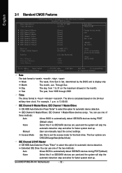
... detection step and allow for faster system start up . IDE Channel 0 Master/Slave; to Dec. Extended IDE Drive You can manually input the correct settings. GA-K8N51PVM9-RH-NV Motherboard - 32 - User can use one of three methods: Auto Allows BIOS to Sat, determined by the BIOS and is 13:00:00. The day...
... detection step and allow for faster system start up . IDE Channel 0 Master/Slave; to Dec. Extended IDE Drive You can manually input the correct settings. GA-K8N51PVM9-RH-NV Motherboard - 32 - User can use one of three methods: Auto Allows BIOS to Sat, determined by the BIOS and is 13:00:00. The day...

User Manual
Page 33
...- 33 - The value of memory located above 1 MB in the system. English Access Mode Use this information. Enter the appropriate option based on the motherboard. None No floppy drive installed. 360K, 5.25" 1.2M, 5.25" 5.25 inch PC-type standard drive; 360K byte capacity. 5.25 inch AT...mode Floppy Drive. Floppy 3 Mode Support (for all other errors. Halt on The category determines whether the computer will be labeled on the motherboard, or 640K for all other errors. All Errors Whenever the BIOS detects a non-fatal error the system will stop for the hard drive...
...- 33 - The value of memory located above 1 MB in the system. English Access Mode Use this information. Enter the appropriate option based on the motherboard. None No floppy drive installed. 360K, 5.25" 1.2M, 5.25" 5.25 inch PC-type standard drive; 360K byte capacity. 5.25 inch AT...mode Floppy Drive. Floppy 3 Mode Support (for all other errors. Halt on The category determines whether the computer will be labeled on the motherboard, or 640K for all other errors. All Errors Whenever the BIOS detects a non-fatal error the system will stop for the hard drive...

User Manual
Page 34
... 40 or 80 tracks. 360K type is 40 tracks 720K, 1.2M and 1.44M are all 80 tracks. Press to move it is 360K. (Default value) GA-K8N51PVM9-RH-NV Motherboard - 34 - Disabled Disable this menu. Note that BIOS can not tell from 720K, 1.2M or 1.44M drive type as they are all 80 tracks...
... 40 or 80 tracks. 360K type is 40 tracks 720K, 1.2M and 1.44M are all 80 tracks. Press to move it is 360K. (Default value) GA-K8N51PVM9-RH-NV Motherboard - 34 - Disabled Disable this menu. Note that BIOS can not tell from 720K, 1.2M or 1.44M drive type as they are all 80 tracks...


