User Guide
Page 1
..., to Control Panel > System and Security > Administrative Tools > Computer Management >Storage > Disk Management. The recommendation is already installed on the system. (1 GB=1024 MB. All motherboard drivers correctly installed B. Refer to take care of the memory currently installed on the SATA hard drive. Intel Rapid Start Technology A. Refer to Set up...
..., to Control Panel > System and Security > Administrative Tools > Computer Management >Storage > Disk Management. The recommendation is already installed on the system. (1 GB=1024 MB. All motherboard drivers correctly installed B. Refer to take care of the memory currently installed on the SATA hard drive. Intel Rapid Start Technology A. Refer to Set up...
User Guide
Page 2
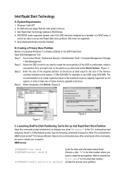
... and move the data from the memory to enable or disable the Intel Rapid Start Technology. Figure 3 Figure 4 D. While in the operating system, insert the motherboard driver disk, go to Application Software\Install Application Software, and select Intel Rapid Start Technology to the results from Start\All Programs\Intel or click...
... and move the data from the memory to enable or disable the Intel Rapid Start Technology. Figure 3 Figure 4 D. While in the operating system, insert the motherboard driver disk, go to Application Software\Install Application Software, and select Intel Rapid Start Technology to the results from Start\All Programs\Intel or click...
User Guide
Page 3
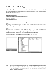
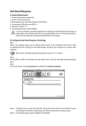
... Internet to obtain their data while your computer when completed. Normal network connection B. Configuring Intel Smart Connect Technology Step 1: After installing the operating system and motherboard drivers, install the Intel Smart Connect Technology application. Look for S3 mode only. System Requirements 1.
... Internet to obtain their data while your computer when completed. Normal network connection B. Configuring Intel Smart Connect Technology Step 1: After installing the operating system and motherboard drivers, install the Intel Smart Connect Technology application. Look for S3 mode only. System Requirements 1.
User Guide
Page 5
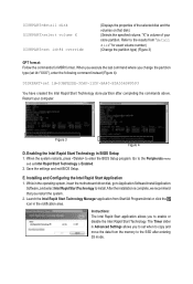
... Technology Step 1: While in the operating system, use the "Xpress Install" function of the hard disk. j k (Note 1) The SSD works as a cache of the motherboard driver disk to install all original data on the hard disk will be lost once you use an SSD larger than 64 GB, the space... computer when completed. Step 2: Find the IRST icon in BIOS Setup 4. The maximum cache memory size is 11.0 or above. An Intel Chipset-based motherboard 2. Restart your data. (Note 2) The operating system must be used for the Intel SATA controllers in the notification area and double-click it to the...
... Technology Step 1: While in the operating system, use the "Xpress Install" function of the hard disk. j k (Note 1) The SSD works as a cache of the motherboard driver disk to install all original data on the hard disk will be lost once you use an SSD larger than 64 GB, the space... computer when completed. Step 2: Find the IRST icon in BIOS Setup 4. The maximum cache memory size is 11.0 or above. An Intel Chipset-based motherboard 2. Restart your data. (Note 2) The operating system must be used for the Intel SATA controllers in the notification area and double-click it to the...
User Manual
Page 3
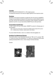
... in this : "REV: X.X." For product-related information, check on our website at: http://www.gigabyte.com Identifying Your Motherboard Revision The revision number on your motherboard revision before updating motherboard BIOS, drivers, or when looking for technical information. Disclaimer Information in this manual may be reproduced,... without prior notice. Documentation Classifications In order to their respective owners. All rights reserved. Check your motherboard looks like this manual is protected by GIGABYTE without GIGABYTE's prior written permission. Example:
... in this : "REV: X.X." For product-related information, check on our website at: http://www.gigabyte.com Identifying Your Motherboard Revision The revision number on your motherboard revision before updating motherboard BIOS, drivers, or when looking for technical information. Disclaimer Information in this manual may be reproduced,... without prior notice. Documentation Classifications In order to their respective owners. All rights reserved. Check your motherboard looks like this manual is protected by GIGABYTE without GIGABYTE's prior written permission. Example:
User Manual
Page 4
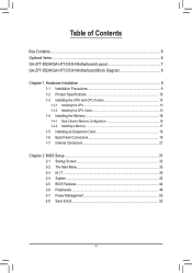
Table of Contents Box Contents...6 Optional Items...6 GA-Z77-DS3H/GA-H77-DS3H Motherboard Layout 7 GA-Z77-DS3H/GA-H77-DS3H Motherboard Block Diagram 8 Chapter 1 Hardware Installation 9 1-1 Installation Precautions 9 1-2 Product Specifications 10 1-3 Installing the CPU and CPU Cooler 13 1-3-1 Installing the CPU 13 1-3-2 Installing the CPU Cooler ...
Table of Contents Box Contents...6 Optional Items...6 GA-Z77-DS3H/GA-H77-DS3H Motherboard Layout 7 GA-Z77-DS3H/GA-H77-DS3H Motherboard Block Diagram 8 Chapter 1 Hardware Installation 9 1-1 Installation Precautions 9 1-2 Product Specifications 10 1-3 Installing the CPU and CPU Cooler 13 1-3-1 Installing the CPU 13 1-3-2 Installing the CPU Cooler ...
User Manual
Page 6
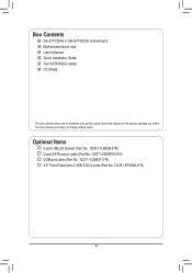
User's Manual ;; Motherboard driver disk ;; Optional Items 2-port USB 2.0 bracket (Part No. 12CR1-1UB030-5*R) 2-port SATA power cable (Part No. 12CF1-2SERPW-0*R) COM port cable (Part No. 12CF1-1CM001-3*R) 3.5" Front Panel with 2 USB 3.0/2.0 ports (Part No. 12CR1-FPX582-0*R) - 6 - Quick Installation Guide ;; Two SATA 6Gb/s cables ;; The box contents are for reference only and the actual items shall depend on the product package you obtain. Box Contents ;; GA-Z77-DS3H or GA-H77-DS3H motherboard ;; I/O Shield The box contents above are subject to change without notice.
User's Manual ;; Motherboard driver disk ;; Optional Items 2-port USB 2.0 bracket (Part No. 12CR1-1UB030-5*R) 2-port SATA power cable (Part No. 12CF1-2SERPW-0*R) COM port cable (Part No. 12CF1-1CM001-3*R) 3.5" Front Panel with 2 USB 3.0/2.0 ports (Part No. 12CR1-FPX582-0*R) - 6 - Quick Installation Guide ;; Two SATA 6Gb/s cables ;; The box contents are for reference only and the actual items shall depend on the product package you obtain. Box Contents ;; GA-Z77-DS3H or GA-H77-DS3H motherboard ;; I/O Shield The box contents above are subject to change without notice.
User Manual
Page 7
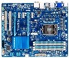
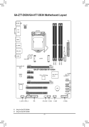
GA-Z77-DS3H/GA-H77-DS3H Motherboard Layout KB_MS_USB ATX_12V DVI VGA LGA1155 HDMI ATX R_USB30 SYS_FAN2 USB_LAN AUDIO CPU_FAN SYS_FAN3 mSATA DDR3_4 DDR3_2 DDR3_3 DDR3_1 F_USB30 Atheros GbE LAN CODEC PCIEX16 PCIEX1_1 GA-Z77-DS3H/GA-H77-DS3H PCIEX1_2 PCIe to PCI Bridge Intel® Z77j/ H77k PCIEX4 iTE Super I/O PCI1 BAT PCI2 COMA B_BIOS M_BIOS SATA3 0 1 SATA2 2 3 4 CLR_CMOS F_AUDIO SPDIF_O TPM SYS_FAN1 F_USB2 F_USB1 F_PANEL j Only for GA-H77-DS3H. - 7 - k Only for GA-Z77-DS3H.
GA-Z77-DS3H/GA-H77-DS3H Motherboard Layout KB_MS_USB ATX_12V DVI VGA LGA1155 HDMI ATX R_USB30 SYS_FAN2 USB_LAN AUDIO CPU_FAN SYS_FAN3 mSATA DDR3_4 DDR3_2 DDR3_3 DDR3_1 F_USB30 Atheros GbE LAN CODEC PCIEX16 PCIEX1_1 GA-Z77-DS3H/GA-H77-DS3H PCIEX1_2 PCIe to PCI Bridge Intel® Z77j/ H77k PCIEX4 iTE Super I/O PCI1 BAT PCI2 COMA B_BIOS M_BIOS SATA3 0 1 SATA2 2 3 4 CLR_CMOS F_AUDIO SPDIF_O TPM SYS_FAN1 F_USB2 F_USB1 F_PANEL j Only for GA-H77-DS3H. - 7 - k Only for GA-Z77-DS3H.
User Manual
Page 8
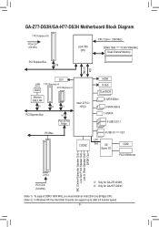
k Only for GA-H77-DS3H. (Note 1) To support DDR3 1600 MHz, you must install an Intel 22nm (Ivy Bridge) CPU. (Note 2) In Windows XP, the Intel USB 3.0 ports can .../Subwoofer Speaker Out) Line Out (Front Speaker Out) Line In (Rear Speaker Out) S/PDIF Out 2 PCI PCI CLK (33 MHz) j Only for GA-Z77-DS3H. GA-Z77-DS3H/GA-H77-DS3H Motherboard Block Diagram 1 PCI Express x16 PCIe CLK (100 MHz) LGA1155 CPU CPU CLK+/- (100 MHz) DDR3 1600 (Note 1)/1333/1066 MHz Dual Channel...
k Only for GA-H77-DS3H. (Note 1) To support DDR3 1600 MHz, you must install an Intel 22nm (Ivy Bridge) CPU. (Note 2) In Windows XP, the Intel USB 3.0 ports can .../Subwoofer Speaker Out) Line Out (Front Speaker Out) Line In (Rear Speaker Out) S/PDIF Out 2 PCI PCI CLK (33 MHz) j Only for GA-Z77-DS3H. GA-Z77-DS3H/GA-H77-DS3H Motherboard Block Diagram 1 PCI Express x16 PCIe CLK (100 MHz) LGA1155 CPU CPU CLK+/- (100 MHz) DDR3 1600 (Note 1)/1333/1066 MHz Dual Channel...
User Manual
Page 9
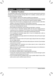
... of electrostatic discharge (ESD). If you are uncertain about any metal leads or connectors. •• It is suitable for the motherboard. •• Prior to installation, do not have a problem related to the use of the product, please consult a certified ...computer technician. - 9 - Hardware Installation Chapter 1 Hardware Installation 1-1 Installation Precautions The motherboard contains numerous delicate electronic circuits and components which can lead to damage to system components as well as physical harm to the user...
... of electrostatic discharge (ESD). If you are uncertain about any metal leads or connectors. •• It is suitable for the motherboard. •• Prior to installation, do not have a problem related to the use of the product, please consult a certified ...computer technician. - 9 - Hardware Installation Chapter 1 Hardware Installation 1-1 Installation Precautions The motherboard contains numerous delicate electronic circuits and components which can lead to damage to system components as well as physical harm to the user...
User Manual
Page 13
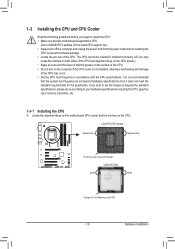
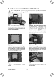
..., otherwise overheating and damage of the CPU Socket LGA1155 CPU Notch Notch Triangle Pin One Marking on the CPU. Locate the alignment keys on the motherboard CPU socket and the notches on the CPU - 13 - 1-3 Installing the CPU and CPU Cooler Read the following guidelines before you begin to ... the standard requirements for the latest CPU support list.) •• Always turn on the computer if the CPU cooler is not recommended that the motherboard supports the CPU. (Go to prevent hardware damage. •• Locate the pin one of the CPU. •• Do not turn off ...
..., otherwise overheating and damage of the CPU Socket LGA1155 CPU Notch Notch Triangle Pin One Marking on the CPU. Locate the alignment keys on the motherboard CPU socket and the notches on the CPU - 13 - 1-3 Installing the CPU and CPU Cooler Read the following guidelines before you begin to ... the standard requirements for the latest CPU support list.) •• Always turn on the computer if the CPU cooler is not recommended that the motherboard supports the CPU. (Go to prevent hardware damage. •• Locate the pin one of the CPU. •• Do not turn off ...
User Manual
Page 14
... CPU is properly inserted, use one corner of the load plate is under the shoulder screw. Step 5: Push the CPU socket lever back into the motherboard CPU socket.
... CPU is properly inserted, use one corner of the load plate is under the shoulder screw. Step 5: Push the CPU socket lever back into the motherboard CPU socket.
User Manual
Page 15
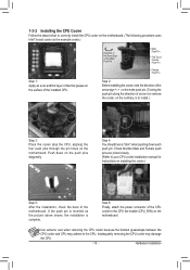
Check that the Male and Female push pins are joined closely. (Refer to your CPU cooler installation manual for instructions on the motherboard. Inadequately removing the CPU cooler may adhere to remove the cooler, on the contrary, is complete. Step 6: Finally, attach the power connector of the CPU ... cooler, note the direction of the arrow sign on the male push pin. (Turning the push pin along the direction of thermal grease on the motherboard. If the push pin is inserted as the example cooler.) Direction of the Arrow Sign on the Male Push Pin Male Push Pin The Top...
Check that the Male and Female push pins are joined closely. (Refer to your CPU cooler installation manual for instructions on the motherboard. Inadequately removing the CPU cooler may adhere to remove the cooler, on the contrary, is complete. Step 6: Finally, attach the power connector of the CPU ... cooler, note the direction of the arrow sign on the male push pin. (Turning the push pin along the direction of thermal grease on the motherboard. If the push pin is inserted as the example cooler.) Direction of the Arrow Sign on the Male Push Pin Male Push Pin The Top...
User Manual
Page 16
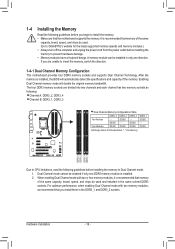
... DDR3_1 Due to insert the memory, switch the direction. 1-4-1 Dual Channel Memory Configuration This motherboard provides four DDR3 memory sockets and supports Dual Channel Technology. After the memory is installed. 2. Dual Channel mode cannot be used . (Go to GIGABYTE's website for the latest supported memory speeds and memory modules.) •• Always...
... DDR3_1 Due to insert the memory, switch the direction. 1-4-1 Dual Channel Memory Configuration This motherboard provides four DDR3 memory sockets and supports Dual Channel Technology. After the memory is installed. 2. Dual Channel mode cannot be used . (Go to GIGABYTE's website for the latest supported memory speeds and memory modules.) •• Always...
User Manual
Page 17
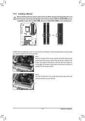
... DIMM A DDR3 memory module has a notch, so it vertically into place when the memory module is securely inserted. - 17 - Place the memory module on this motherboard. DDR3 and DDR2 DIMMs are not compatible to each other or DDR DIMMs. Be sure to the memory module. Spread the retaining clips at both...
... DIMM A DDR3 memory module has a notch, so it vertically into place when the memory module is securely inserted. - 17 - Place the memory module on this motherboard. DDR3 and DDR2 DIMMs are not compatible to each other or DDR DIMMs. Be sure to the memory module. Spread the retaining clips at both...
User Manual
Page 18
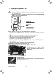
... card until it is fully inserted into the slot. 4. If necessary, go to BIOS Setup to install an expansion card: •• Make sure the motherboard supports the expansion card. 1-5 Installing an Expansion Card Read the following guidelines before installing an expansion card to correctly install your expansion card in the...
... card until it is fully inserted into the slot. 4. If necessary, go to BIOS Setup to install an expansion card: •• Make sure the motherboard supports the expansion card. 1-5 Installing an Expansion Card Read the following guidelines before installing an expansion card to correctly install your expansion card in the...
User Manual
Page 19
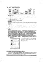
... in operating system environment only, but the actual resolutions supported are dependent on your HDMI-supported monitor. Use this port for the Onboard Graphics: This motherboard provides three video output ports: D-Sub, DVI-D, and HDMI. It also supports up to connect a PS/2 mouse or keyboard. The maximum supported resolution is an...
... in operating system environment only, but the actual resolutions supported are dependent on your HDMI-supported monitor. Use this port for the Onboard Graphics: This motherboard provides three video output ports: D-Sub, DVI-D, and HDMI. It also supports up to connect a PS/2 mouse or keyboard. The maximum supported resolution is an...
User Manual
Page 20
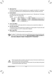
... jack. Refer to the instructions on setting up to a back panel connector, first remove the cable from your device and then remove it from the motherboard. •• When removing the cable, pull it side to side to use an HD front panel audio module and enable the multichannel audio feature...
... jack. Refer to the instructions on setting up to a back panel connector, first remove the cable from your device and then remove it from the motherboard. •• When removing the cable, pull it side to side to use an HD front panel audio module and enable the multichannel audio feature...
User Manual
Page 21
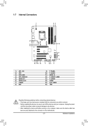
... and your devices are compliant with the connectors you wish to connect. •• Before installing the devices, be sure to the connector on the motherboard. - 21 - Hardware Installation 1-7 Internal Connectors 1 42 4 3 13 7 5 6 15 10 11 14 16 4 12 8 9 1) ATX_12V 2) ATX 3) CPU_FAN 4) SYS_FAN1/2/3 5) SATA3 0/1 6) SATA2 2/3/4 7) mSATA 8) BAT 9) F_PANEL 10) F_AUDIO 11...
... and your devices are compliant with the connectors you wish to connect. •• Before installing the devices, be sure to the connector on the motherboard. - 21 - Hardware Installation 1-7 Internal Connectors 1 42 4 3 13 7 5 6 15 10 11 14 16 4 12 8 9 1) ATX_12V 2) ATX 3) CPU_FAN 4) SYS_FAN1/2/3 5) SATA3 0/1 6) SATA2 2/3/4 7) mSATA 8) BAT 9) F_PANEL 10) F_AUDIO 11...
User Manual
Page 22
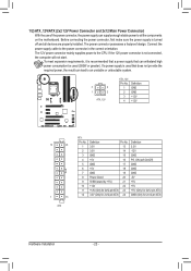
... mainly supplies power to the power connector in the correct orientation. If the 12V power connector is turned off and all the components on the motherboard. 1/2) ATX_12V/ATX (2x2 12V Power Connector and 2x12 Main Power Connector) With the use of the power connector, the power supply can supply enough stable...
... mainly supplies power to the power connector in the correct orientation. If the 12V power connector is turned off and all the components on the motherboard. 1/2) ATX_12V/ATX (2x2 12V Power Connector and 2x12 Main Power Connector) With the use of the power connector, the power supply can supply enough stable...


