Manual
Page 4
Table of Contents GA-H61M-DS2 Motherboard Layout 5 GA-H61M-DS2 Motherboard Block Diagram 6 Chapter 1 Hardware Installation 7 1-1 Installation Precautions 7 1-2 Product Specifications 8 1-3 Installing the CPU 10 1-4 Installing the Memory 11 1-5 Installing an ...Startup Screen 20 2-2 The Main Menu 21 2-3 MB Intelligent Tweaker(M.I.T 22 2-4 Standard CMOS Features 28 2-5 Advanced BIOS Features 29 2-6 Integrated Peripherals 31 2-7 Power Management Setup 32 2-8 PC Health Status 34 2-9 Load Fail-Safe Defaults 35 2-10 Load Optimized Defaults 36 2-11 Set Supervisor/User Password 36 2-12 ...
Table of Contents GA-H61M-DS2 Motherboard Layout 5 GA-H61M-DS2 Motherboard Block Diagram 6 Chapter 1 Hardware Installation 7 1-1 Installation Precautions 7 1-2 Product Specifications 8 1-3 Installing the CPU 10 1-4 Installing the Memory 11 1-5 Installing an ...Startup Screen 20 2-2 The Main Menu 21 2-3 MB Intelligent Tweaker(M.I.T 22 2-4 Standard CMOS Features 28 2-5 Advanced BIOS Features 29 2-6 Integrated Peripherals 31 2-7 Power Management Setup 32 2-8 PC Health Status 34 2-9 Load Fail-Safe Defaults 35 2-10 Load Optimized Defaults 36 2-11 Set Supervisor/User Password 36 2-12 ...
Manual
Page 7
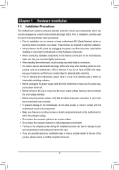
... the motherboard, do not remove or break motherboard S/N (Serial Number) sticker or warranty sticker provided by unplugging the power cord from the power outlet before installing or removing the motherboard or other hardware components. •• When connecting hardware components to the internal... components placed on the motherboard or within an electrostatic shielding container. •• Before unplugging the power supply cable from the motherboard, make sure the power supply voltage has been set according to the local voltage standard. •• Before using the product...
... the motherboard, do not remove or break motherboard S/N (Serial Number) sticker or warranty sticker provided by unplugging the power cord from the power outlet before installing or removing the motherboard or other hardware components. •• When connecting hardware components to the internal... components placed on the motherboard or within an electrostatic shielding container. •• Before unplugging the power supply cable from the motherboard, make sure the power supply voltage has been set according to the local voltage standard. •• Before using the product...
Manual
Page 8
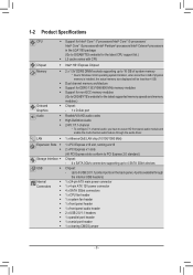
...® Core™ i3 processors/Intel® Pentium® processors/Intel® Celeron® processors in the LGA1155 package (Go to GIGABYTE's website for the latest CPU support list.) ŠŠ L3 cache varies with CPU Chipset ŠŠ Intel® H61 Express ... use an HD front panel audio module and enable the multi-channel audio feature through the internal USB headers) 1 x 24-pin ATX main power connector 1 x 4-pin ATX 12V power connector 4 x SATA 3Gb/s connectors 1 x CPU fan header 1 x system fan header 1 x front panel header 1 x front panel audio header 2 x USB 2.0/1.1 ...
...® Core™ i3 processors/Intel® Pentium® processors/Intel® Celeron® processors in the LGA1155 package (Go to GIGABYTE's website for the latest CPU support list.) ŠŠ L3 cache varies with CPU Chipset ŠŠ Intel® H61 Express ... use an HD front panel audio module and enable the multi-channel audio feature through the internal USB headers) 1 x 24-pin ATX main power connector 1 x 4-pin ATX 12V power connector 4 x SATA 3Gb/s connectors 1 x CPU fan header 1 x system fan header 1 x front panel header 1 x front panel audio header 2 x USB 2.0/1.1 ...
Manual
Page 10
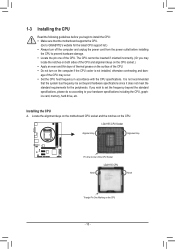
... it does not meet the standard requirements for the latest CPU support list.) •• Always turn off the computer and unplug the power cord from the power outlet before you begin to install the CPU: •• Make sure that the system bus frequency be inserted if oriented incorrectly. ...the CPU. •• Do not turn on the computer if the CPU cooler is not recommended that the motherboard supports the CPU. (Go to GIGABYTE's website for the peripherals. Locate the alignment keys on the motherboard CPU socket and the notches on the CPU - 10 - It is not installed,...
... it does not meet the standard requirements for the latest CPU support list.) •• Always turn off the computer and unplug the power cord from the power outlet before you begin to install the CPU: •• Make sure that the system bus frequency be inserted if oriented incorrectly. ...the CPU. •• Do not turn on the computer if the CPU cooler is not recommended that the motherboard supports the CPU. (Go to GIGABYTE's website for the peripherals. Locate the alignment keys on the motherboard CPU socket and the notches on the CPU - 10 - It is not installed,...
Manual
Page 11
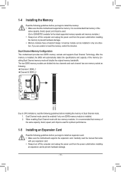
... switch the direction. A memory module can be installed in Dual Channel mode. 111 Dual Channel mode cannot be used . (Go to GIGABYTE's website for optimum performance. 1-5 Installing an Expansion Card Read the following guidelines before you begin to install the memory: •• Make...installed. 222 When enabling Dual Channel mode with your expansion card. •• Always turn off the computer and unplug the power cord from the power outlet before installing the memory to prevent hardware damage. •• Memory modules have a foolproof design. 1-4 Installing the ...
... switch the direction. A memory module can be installed in Dual Channel mode. 111 Dual Channel mode cannot be used . (Go to GIGABYTE's website for optimum performance. 1-5 Installing an Expansion Card Read the following guidelines before you begin to install the memory: •• Make...installed. 222 When enabling Dual Channel mode with your expansion card. •• Always turn off the computer and unplug the power cord from the power outlet before installing the memory to prevent hardware damage. •• Memory modules have a foolproof design. 1-4 Installing the ...
Manual
Page 13
Unplug the power cord from the power outlet to prevent damage to the devices. •• After installing the device and before connecting external devices: •• First make sure the device ...
Unplug the power cord from the power outlet to prevent damage to the devices. •• After installing the device and before connecting external devices: •• First make sure the device ...
Manual
Page 14
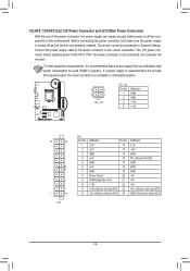
...Pin No. 1 2 3 4 5 6 7 8 9 10 11 12 Definition Pin No. 3.3V 13 3.3V 14 GND 15 +5V 16 GND 17 +5V 18 GND 19 Power Good 20 5VSB (stand by +5V) 21 +12V 22 +12V (Only for 2x12-pin ATX) 23 3.3V (Only for 2x12-pin ATX) 24 Definition 3.3V... 1/2) ATX_12V/ATX (2x2 12V Power Connector and 2x12 Main Power Connector) With the use of the power connector, the power supply can supply enough stable power to all devices are properly installed. The power connector possesses a foolproof design. Before connecting the power connector, first make sure the power supply is used (500W or ...
...Pin No. 1 2 3 4 5 6 7 8 9 10 11 12 Definition Pin No. 3.3V 13 3.3V 14 GND 15 +5V 16 GND 17 +5V 18 GND 19 Power Good 20 5VSB (stand by +5V) 21 +12V 22 +12V (Only for 2x12-pin ATX) 23 3.3V (Only for 2x12-pin ATX) 24 Definition 3.3V... 1/2) ATX_12V/ATX (2x2 12V Power Connector and 2x12 Main Power Connector) With the use of the power connector, the power supply can supply enough stable power to all devices are properly installed. The power connector possesses a foolproof design. Before connecting the power connector, first make sure the power supply is used (500W or ...

Manual
Page 16
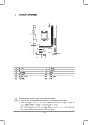
...): M_SATA Connects to turn off (S5). suing a beep code. The front panel design may configure the way to the power switch on the chassis front panel. F_AUDIO(H) F_PANEL(NH) 2 1 20 F_PANEL 19 (H61M-D2) HD+ HD- The LED is off when the system is reading or writing data. •• RES (Reset...
...): M_SATA Connects to turn off (S5). suing a beep code. The front panel design may configure the way to the power switch on the chassis front panel. F_AUDIO(H) F_PANEL(NH) 2 1 20 F_PANEL 19 (H61M-D2) HD+ HD- The LED is off when the system is reading or writing data. •• RES (Reset...
Manual
Page 17
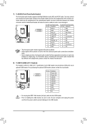
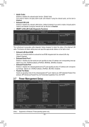
...Make sure the wire assignments of the module connector match the pin assignments of a single plug. Definition 1 MIC2_L 9 1 10 2 2 GND 3 MIC2_R 1 MIC 2 GND 3 MIC Power 4 -ACZ_DET 4 NC 5 LINE2_R 5 Line Out (R) 6 GND 6 NC 7 FAUDIO_JD 7 NC 8 No Pin 8 No Pin 9 LINE2_L 9 Line Out (L) 10 GND 10 NC... panel audio header supports HD audio by default. •• Audio signals will make the device unable to the USB bracket. - 17 - Definition 1 Power (5V) 9 1 10 2 2 Power (5V) 3 USB DX- 4 USB DY- 5 USB DX+ 6 USB DY+ 7 GND 8 GND 9 No Pin 10 NC •• ...
...Make sure the wire assignments of the module connector match the pin assignments of a single plug. Definition 1 MIC2_L 9 1 10 2 2 GND 3 MIC2_R 1 MIC 2 GND 3 MIC Power 4 -ACZ_DET 4 NC 5 LINE2_R 5 Line Out (R) 6 GND 6 NC 7 FAUDIO_JD 7 NC 8 No Pin 8 No Pin 9 LINE2_L 9 Line Out (L) 10 GND 10 NC... panel audio header supports HD audio by default. •• Audio signals will make the device unable to the USB bracket. - 17 - Definition 1 Power (5V) 9 1 10 2 2 Power (5V) 3 USB DX- 4 USB DY- 5 USB DX+ 6 USB DY+ 7 GND 8 GND 9 No Pin 10 NC •• ...
Manual
Page 19
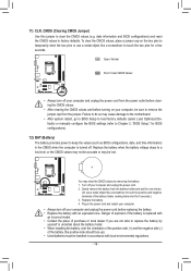
...short for 5 seconds.) 333 Replace the battery. 444 Plug in the power cord and restart your computer. •• Always turn off your computer and unplug the power cord. 222 Gently remove the battery from the power outlet before clearing the CMOS values. •• After clearing the CMOS...(refer to Chapter 2, "BIOS Setup," for BIOS configurations). 12) BAT (Battery) The battery provides power to replace the battery by removing the battery: 111 Turn off your computer and unplug the power cord from the battery holder and wait for a few seconds. 11) CLR_CMOS (Clearing CMOS Jumper) ...
...short for 5 seconds.) 333 Replace the battery. 444 Plug in the power cord and restart your computer. •• Always turn off your computer and unplug the power cord. 222 Gently remove the battery from the power outlet before clearing the CMOS values. •• After clearing the CMOS...(refer to Chapter 2, "BIOS Setup," for BIOS configurations). 12) BAT (Battery) The battery provides power to replace the battery by removing the battery: 111 Turn off your computer and unplug the power cord from the battery holder and wait for a few seconds. 11) CLR_CMOS (Clearing CMOS Jumper) ...
Manual
Page 20
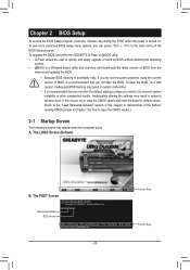
...BIOS Setup To access the BIOS Setup program, press the key during the POST when the power is recommended that you not alter the default settings (unless you need to) to prevent ...system instability or other unexpected results. To upgrade the BIOS, use either the GIGABYTE Q-Flash or @BIOS utility. •• Q-Flash allows the user to quickly and easily ... can press + in system malfunction. •• It is recommended that you do it is turned on. A. H61M-DS2 E4 . . . . : BIOS Setup : XpressRecovery2 : Boot Menu : Qflash 07/14/2011-H61-7A89XG05C-00 Function...
...BIOS Setup To access the BIOS Setup program, press the key during the POST when the power is recommended that you not alter the default settings (unless you need to) to prevent ...system instability or other unexpected results. To upgrade the BIOS, use either the GIGABYTE Q-Flash or @BIOS utility. •• Q-Flash allows the user to quickly and easily ... can press + in system malfunction. •• It is recommended that you do it is turned on. A. H61M-DS2 E4 . . . . : BIOS Setup : XpressRecovery2 : Boot Menu : Qflash 07/14/2011-H61-7A89XG05C-00 Function...

Manual
Page 21
...: E4) CMOS Setup Utility-Copyright (C) 1984-2011 Award Software MB Intelligent Tweaker(M.I.T.) Standard CMOS Features Advanced BIOS Features Integrated Peripherals Power Management Setup PC Health Status Load Fail-Safe Defaults Load Optimized Defaults Set Supervisor Password Set User Password Save & Exit Setup Exit Without Saving...
...: E4) CMOS Setup Utility-Copyright (C) 1984-2011 Award Software MB Intelligent Tweaker(M.I.T.) Standard CMOS Features Advanced BIOS Features Integrated Peripherals Power Management Setup PC Health Status Load Fail-Safe Defaults Load Optimized Defaults Set Supervisor Password Set User Password Save & Exit Setup Exit Without Saving...
Manual
Page 23
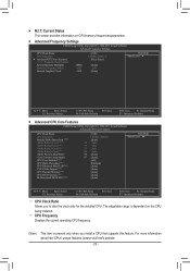
...(R) Turbo Boost Tech. (Note) -Turbo Ratio(1-Core)(Note) 34 -Turbo Ratio(2-Core)(Note) 33 -Turbo Ratio(3-Core)(Note) 33 -Turbo Ratio(4-Core)(Note) 32 -Turbo Power Limit(Watts) 95 -Core Current Limit(Amps) 97 CPU Cores Enabled (Note) CPU Multi-Threading (Note) CPU Enhanced Halt (C1E) (Note) C3/C6 State Support...
...(R) Turbo Boost Tech. (Note) -Turbo Ratio(1-Core)(Note) 34 -Turbo Ratio(2-Core)(Note) 33 -Turbo Ratio(3-Core)(Note) 33 -Turbo Ratio(4-Core)(Note) 32 -Turbo Power Limit(Watts) 95 -Core Current Limit(Amps) 97 CPU Cores Enabled (Note) CPU Multi-Threading (Note) CPU Enhanced Halt (C1E) (Note) C3/C6 State Support...

Manual
Page 24
.... Depending on CPU loading, Intel EIST technology can dynamically and effectively lower the CPU voltage and core frequency to reduce the power. For more enhanced power-saving state than C1. Auto lets the BIOS automatically configure this setting. (Default: Auto) C3/C6 State Support (Note)...support multi-processor mode. (Default: Enabled) CPU Enhanced Halt (C1E) (Note) Enables or disables Intel CPU Enhanced Halt (C1E) function, a CPU power-saving function in system halt state. Intel(R) Turbo Boost Tech. (Note) Allows you to determine whether to enable all CPU cores. (Default) 1 ...
.... Depending on CPU loading, Intel EIST technology can dynamically and effectively lower the CPU voltage and core frequency to reduce the power. For more enhanced power-saving state than C1. Auto lets the BIOS automatically configure this setting. (Default: Auto) C3/C6 State Support (Note)...support multi-processor mode. (Default: Enabled) CPU Enhanced Halt (C1E) (Note) Enables or disables Intel CPU Enhanced Halt (C1E) function, a CPU power-saving function in system halt state. Intel(R) Turbo Boost Tech. (Note) Allows you to determine whether to enable all CPU cores. (Default) 1 ...
Manual
Page 32
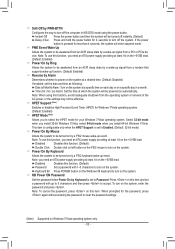
... (Enhanced Parallel Port), ECP (Extended Capabilities Port), ECP+EPP. 2-7 Power Management Setup CMOS Setup Utility-Copyright (C) 1984-2011 Award Software Power Management Setup Soft-Off by PWR-BTTN PME Event Wake Up Power On by Ring Resume by Alarm x Date (of Month) Alarm x... Time (hh:mm:ss) Alarm HPET Support (Note) HPET Mode (Note) Power On By Mouse Power On By Keyboard x KB Power ON Password AC Back Function ErP Support [Instant-Off] [Enabled] [Enabled] [Disabled] Everyday 0 : 0 : 0 [Enabled] [32...
... (Enhanced Parallel Port), ECP (Extended Capabilities Port), ECP+EPP. 2-7 Power Management Setup CMOS Setup Utility-Copyright (C) 1984-2011 Award Software Power Management Setup Soft-Off by PWR-BTTN PME Event Wake Up Power On by Ring Resume by Alarm x Date (of Month) Alarm x... Time (hh:mm:ss) Alarm HPET Support (Note) HPET Mode (Note) Power On By Mouse Power On By Keyboard x KB Power ON Password AC Back Function ErP Support [Instant-Off] [Enabled] [Enabled] [Disabled] Everyday 0 : 0 : 0 [Enabled] [32...
Manual
Page 33
...use this function, avoid inadequate shutdown from a PCI or PCIe device. Disabled Disables this item. Note: To cancel the password, press on the system. Power On By Keyboard Allows the system to be awakened from an ACPI sleep state by a wake-up signal from an ACPI sleep state by a PS...will enter suspend mode. Press on the system. This item is configurable only when the HPET Support is set to Enabled. (Default: 32-bit mode) Power On By Mouse Allows the system to be awakened from a modem that supports wake-up function. (Default: Enabled) Resume by a PS/2 keyboard wake-...
...use this function, avoid inadequate shutdown from a PCI or PCIe device. Disabled Disables this item. Note: To cancel the password, press on the system. Power On By Keyboard Allows the system to be awakened from an ACPI sleep state by a wake-up signal from an ACPI sleep state by a PS...will enter suspend mode. Press on the system. This item is configurable only when the HPET Support is set to Enabled. (Default: 32-bit mode) Power On By Mouse Allows the system to be awakened from a modem that supports wake-up function. (Default: Enabled) Resume by a PS/2 keyboard wake-...

Manual
Page 34
...shutdown) state. (Default: Disabled) Note: When this field will show "Yes", otherwise it will show "No". Enabled clears the record of the AC power. If the system chassis cover is turned on LAN. 2-8 PC Health Status CMOS Setup Utility-Copyright (C) 1984-2011 Award Software PC Health Status Reset Case... the motherboard CI header. To clear the chassis intrusion status record, set to its last known awake state upon the return of power from an AC power loss. Soft-Off The system stays off upon the return of previous chassis intrusion status and the Case Opened field will show "...
...shutdown) state. (Default: Disabled) Note: When this field will show "Yes", otherwise it will show "No". Enabled clears the record of the AC power. If the system chassis cover is turned on LAN. 2-8 PC Health Status CMOS Setup Utility-Copyright (C) 1984-2011 Award Software PC Health Status Reset Case... the motherboard CI header. To clear the chassis intrusion status record, set to its last known awake state upon the return of power from an AC power loss. Soft-Off The system stays off upon the return of previous chassis intrusion status and the Case Opened field will show "...
Manual
Page 35
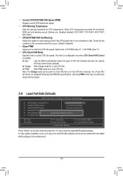
...(M.I.T.) Load Fail-Safe Defaults Standard CMOS Features Load Optimized Defaults Advanced BIOS Features Set Supervisor Password Integrated Peripherals Set User Password Power Management Setup PC Health Status Load Fail-Safe DefaultsS(Yav/eN&)? Options are : Disabled (default), 60oC/140oF, 70oC/158oF, 80oC/176oF, 90oC/194oF. In...
...(M.I.T.) Load Fail-Safe Defaults Standard CMOS Features Load Optimized Defaults Advanced BIOS Features Set Supervisor Password Integrated Peripherals Set User Password Power Management Setup PC Health Status Load Fail-Safe DefaultsS(Yav/eN&)? Options are : Disabled (default), 60oC/140oF, 70oC/158oF, 80oC/176oF, 90oC/194oF. In...
Manual
Page 36
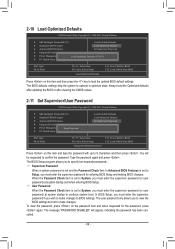
...CMOS Features Load Optimized Defaults Advanced BIOS Features Set Supervisor Password Integrated Peripherals Set User Password Power Management Setup PC Health Status Load Optimized DefaultsS(aYve/N&)?ENxit Setup Exit Without Saving ESC: Quit F8: Q-Flash...61565; MB Intelligent Tweaker(M.I .T.) Standard CMOS Features Advanced BIOS Features Integrated Peripherals Power Management SetupEnter Password: PC Health Status Load Fail-Safe Defaults Load Optimized Defaults Set Supervisor Password Set User Password Save...
...CMOS Features Load Optimized Defaults Advanced BIOS Features Set Supervisor Password Integrated Peripherals Set User Password Power Management Setup PC Health Status Load Optimized DefaultsS(aYve/N&)?ENxit Setup Exit Without Saving ESC: Quit F8: Q-Flash...61565; MB Intelligent Tweaker(M.I .T.) Standard CMOS Features Advanced BIOS Features Integrated Peripherals Power Management SetupEnter Password: PC Health Status Load Fail-Safe Defaults Load Optimized Defaults Set Supervisor Password Set User Password Save...
Manual
Page 37
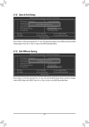
... BIOS Features Load Optimized Defaults Save to CMOS and EXITSe(Yt S/Nup)?erYvisor Password Integrated Peripherals Set User Password Power Management Setup Save & Exit Setup PC Health Status Exit Without Saving ESC: Quit F8: Q-Flash Select Item F10: Save... Advanced BIOS Features Load Optimized Defaults Quit Without Saving (YSe/Nt S)?upNervisor Password Integrated Peripherals Set User Password Power Management Setup Save & Exit Setup PC Health Status Exit Without Saving ESC: Quit F8: Q-Flash Select Item F10: Save &...
... BIOS Features Load Optimized Defaults Save to CMOS and EXITSe(Yt S/Nup)?erYvisor Password Integrated Peripherals Set User Password Power Management Setup Save & Exit Setup PC Health Status Exit Without Saving ESC: Quit F8: Q-Flash Select Item F10: Save... Advanced BIOS Features Load Optimized Defaults Quit Without Saving (YSe/Nt S)?upNervisor Password Integrated Peripherals Set User Password Power Management Setup Save & Exit Setup PC Health Status Exit Without Saving ESC: Quit F8: Q-Flash Select Item F10: Save &...


