Manual
Page 1
GA-H57M-USB3 GA-H55M-USB3 LGA1156 socket motherboard for Intel® Core™ i7 processor family/ Intel® Core™ i5 processor family/ Intel® Core™ i3 processor family User's Manual Rev. 1001 12ME-H57MUB3-1001R
GA-H57M-USB3 GA-H55M-USB3 LGA1156 socket motherboard for Intel® Core™ i7 processor family/ Intel® Core™ i5 processor family/ Intel® Core™ i3 processor family User's Manual Rev. 1001 12ME-H57MUB3-1001R
Manual
Page 2
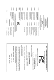
Motherboard GA-H57M-USB3/GA-H55M-USB3 Jan. 14, 2010 Motherboard GA-H57M-USB3/ GA-H55M-USB3 Jan. 14, 2010
Motherboard GA-H57M-USB3/GA-H55M-USB3 Jan. 14, 2010 Motherboard GA-H57M-USB3/ GA-H55M-USB3 Jan. 14, 2010

Manual
Page 3
...when looking for technical information. All rights reserved. Changes to their respective owners. Check your motherboard looks like this manual may be made by any form or by GIGABYTE without GIGABYTE's prior written permission. For example, "REV: 1.0" means the revision of the product, ... is protected by copyright laws and is 1.0. For product-related information, check on our website at: http://www.gigabyte.com.tw Identifying Your Motherboard Revision The revision number on how to assist in any means without prior notice. Example: The trademarks mentioned in ...
...when looking for technical information. All rights reserved. Changes to their respective owners. Check your motherboard looks like this manual may be made by any form or by GIGABYTE without GIGABYTE's prior written permission. For example, "REV: 1.0" means the revision of the product, ... is protected by copyright laws and is 1.0. For product-related information, check on our website at: http://www.gigabyte.com.tw Identifying Your Motherboard Revision The revision number on how to assist in any means without prior notice. Example: The trademarks mentioned in ...
Manual
Page 4
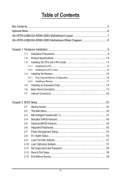
Table of Contents Box Contents...6 Optional Items...6 GA-H57M-USB3/GA-H55M-USB3 Motherboard Layout 7 GA-H57M-USB3/GA-H55M-USB3 Motherboard Block Diagram 8 Chapter 1 Hardware Installation 9 1-1 Installation Precautions 9 1-2 Product Specifications 10 1-3 Installing the CPU and CPU Cooler 13 1-3-1 Installing the CPU 13 1-3-2 Installing the CPU Cooler ...
Table of Contents Box Contents...6 Optional Items...6 GA-H57M-USB3/GA-H55M-USB3 Motherboard Layout 7 GA-H57M-USB3/GA-H55M-USB3 Motherboard Block Diagram 8 Chapter 1 Hardware Installation 9 1-1 Installation Precautions 9 1-2 Product Specifications 10 1-3 Installing the CPU and CPU Cooler 13 1-3-1 Installing the CPU 13 1-3-2 Installing the CPU Cooler ...
Manual
Page 6
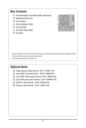
The box contents are for reference only. Box Contents GA-H57M-USB3 or GA-H55M-USB3 motherboard Motherboard driver disk User's Manual Quick Installation Guide One IDE cable Two SATA 3Gb/s cables I/O Shield • The box contents above are subject to change without notice. • The motherboard image is for reference only and the actual items shall depend on...
The box contents are for reference only. Box Contents GA-H57M-USB3 or GA-H55M-USB3 motherboard Motherboard driver disk User's Manual Quick Installation Guide One IDE cable Two SATA 3Gb/s cables I/O Shield • The box contents above are subject to change without notice. • The motherboard image is for reference only and the actual items shall depend on...
Manual
Page 7
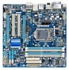
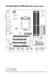
GA-H57M-USB3/GA-H55M-USB3 Motherboard Layout KB_USB VGA_DVI ATX_12V_2X4 CPU_FAN SYS_FAN DP_HDMI_SPDIF ESATA_1394_USB USB30_LAN NEC D720200F1 LGA1156 PHASE LED IT8720 IDE ATX FDD AUDIO F_AUDIO PCIEX16 RTL8111D SPDIF_O SPDIF_I CODEC PCI1 PCI2 PCIEX4_X1 BAT GA-H57M-USB3/ GA-H55M-USB3 DDR3_2 DDR3_1 DDR3_4 DDR3_3 TSB43AB23 Intel® H57 j Intel® H55 k GIGABYTE SATA2 B_BIOS SATA2_0 M_BIOS SATA2_1 SATA2_3 GSATA2_6 SATA2_2 SATA2_4 GSATA2_5 CLR_CMOS CD_IN COMA F_1394 F_USB4j F_USB3 F_USB2 F_USB1 F_PANEL j Only for GA-H55M-USB3. - 7 - k Only for GA-H57M-USB3.
GA-H57M-USB3/GA-H55M-USB3 Motherboard Layout KB_USB VGA_DVI ATX_12V_2X4 CPU_FAN SYS_FAN DP_HDMI_SPDIF ESATA_1394_USB USB30_LAN NEC D720200F1 LGA1156 PHASE LED IT8720 IDE ATX FDD AUDIO F_AUDIO PCIEX16 RTL8111D SPDIF_O SPDIF_I CODEC PCI1 PCI2 PCIEX4_X1 BAT GA-H57M-USB3/ GA-H55M-USB3 DDR3_2 DDR3_1 DDR3_4 DDR3_3 TSB43AB23 Intel® H57 j Intel® H55 k GIGABYTE SATA2 B_BIOS SATA2_0 M_BIOS SATA2_1 SATA2_3 GSATA2_6 SATA2_2 SATA2_4 GSATA2_5 CLR_CMOS CD_IN COMA F_1394 F_USB4j F_USB3 F_USB2 F_USB1 F_PANEL j Only for GA-H55M-USB3. - 7 - k Only for GA-H57M-USB3.
Manual
Page 8
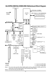
... 3.0. - 8 - GA-H57M-USB3/GA-H55M-USB3 Motherboard Block Diagram 1 PCI Express x16 CPU CLK+/- (133 MHz) PCIe CLK (100 MHz) LGA1156 CPU DDR3 1666 (O.C.)/1333/1066/800 MHz Dual Channel Memory DMI Interface FDI Interface x16 PCI Express Bus x1 Gen 2 2 USB 3.0 Switch PCI Express Bus x1 Gen 1 NEC D720200F1 x4/ X1 x1 x1 RTL8111D RJ45 GIGABYTE... Speaker Out Center/Subwoofer Speaker Out Side Speaker Out MIC Line Out Line In S/PDIF In S/PDIF Out 2 PCI PCI CLK (33 MHz) j Only for GA-H57M-USB3.
... 3.0. - 8 - GA-H57M-USB3/GA-H55M-USB3 Motherboard Block Diagram 1 PCI Express x16 CPU CLK+/- (133 MHz) PCIe CLK (100 MHz) LGA1156 CPU DDR3 1666 (O.C.)/1333/1066/800 MHz Dual Channel Memory DMI Interface FDI Interface x16 PCI Express Bus x1 Gen 2 2 USB 3.0 Switch PCI Express Bus x1 Gen 1 NEC D720200F1 x4/ X1 x1 x1 RTL8111D RJ45 GIGABYTE... Speaker Out Center/Subwoofer Speaker Out Side Speaker Out MIC Line Out Line In S/PDIF In S/PDIF Out 2 PCI PCI CLK (33 MHz) j Only for GA-H57M-USB3.
Manual
Page 9
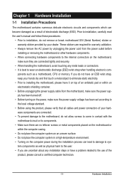
...an ESD wrist strap, keep your hands dry and first touch a metal object to eliminate static electricity. • Prior to installing the motherboard, please have it on top of an antistatic pad or within the computer casing. • Do not place the computer system on ... not place the computer system in a high-temperature environment. • Turning on the computer power during the installation process can become damaged as a motherboard, CPU or memory. Prior to installation, carefully read the user's manual and follow these procedures: • Prior to installation, do not allow screws...
...an ESD wrist strap, keep your hands dry and first touch a metal object to eliminate static electricity. • Prior to installing the motherboard, please have it on top of an antistatic pad or within the computer casing. • Do not place the computer system on ... not place the computer system in a high-temperature environment. • Turning on the computer power during the installation process can become damaged as a motherboard, CPU or memory. Prior to installation, carefully read the user's manual and follow these procedures: • Prior to installation, do not allow screws...
Manual
Page 12
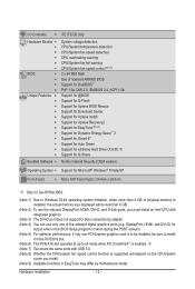
DisplayPort, HDMI, and DVI-D) for GA-H57M-USB3. (Note 1) Due to x4 mode when ATI CrossFireX™ is supported will depend on the CPU/system cooler you install. (Note 9) Available functions in the ... of the onboard digital graphics ports (e.g. j (Note 7) Two share the same ports with integrated graphics. (Note 3) The DVI-D port does not support D-Sub connection by motherboard model. Hardware Installation - 12 -
DisplayPort, HDMI, and DVI-D) for GA-H57M-USB3. (Note 1) Due to x4 mode when ATI CrossFireX™ is supported will depend on the CPU/system cooler you install. (Note 9) Available functions in the ... of the onboard digital graphics ports (e.g. j (Note 7) Two share the same ports with integrated graphics. (Note 3) The DVI-D port does not support D-Sub connection by motherboard model. Hardware Installation - 12 -

Manual
Page 13
... if oriented incorrectly. (Or you may occur. • Set the CPU host frequency in accordance with the CPU specifications. Locate the alignment keys on the motherboard CPU socket and the notches on the CPU - 13 - Hardware Installation It is not installed, otherwise overheating and dam- LGA1156 CPU Socket Alignment Key Alignment... CPU to prevent hardware damage. • Locate the pin one of thermal grease on the computer if the CPU cooler is not recommended that the motherboard supports the CPU. (Go to GIGABYTE's website for the peripherals.
... if oriented incorrectly. (Or you may occur. • Set the CPU host frequency in accordance with the CPU specifications. Locate the alignment keys on the motherboard CPU socket and the notches on the CPU - 13 - Hardware Installation It is not installed, otherwise overheating and dam- LGA1156 CPU Socket Alignment Key Alignment... CPU to prevent hardware damage. • Locate the pin one of thermal grease on the computer if the CPU cooler is not recommended that the motherboard supports the CPU. (Go to GIGABYTE's website for the peripherals.

Manual
Page 14
... the CPU. Step 2: Remove the CPU socket cover as well. Hold your thumb and index fingers. Step 5: Push the CPU socket lever back into the motherboard CPU socket. Then completely lift the CPU socket lever and the metal load plate will be lifted as shown. Step 4: Once the CPU is under...
... the CPU. Step 2: Remove the CPU socket cover as well. Hold your thumb and index fingers. Step 5: Push the CPU socket lever back into the motherboard CPU socket. Then completely lift the CPU socket lever and the metal load plate will be lifted as shown. Step 4: Once the CPU is under...

Manual
Page 15
...attach the power connector of the installed CPU. 1-3-2 Installing the CPU Cooler Follow the steps below to correctly install the CPU cooler on the motherboard. (The following procedure uses Intel® boxed cooler as the picture above shows, the installation is to the CPU. Push down each push ...manual for instructions on installing the cooler.) Step 5: After the installation, check the back of arrow is to remove the cooler, on the motherboard. Use extreme care when removing the CPU cooler because the thermal grease/tape between the CPU cooler and CPU may damage the CPU. -...
...attach the power connector of the installed CPU. 1-3-2 Installing the CPU Cooler Follow the steps below to correctly install the CPU cooler on the motherboard. (The following procedure uses Intel® boxed cooler as the picture above shows, the installation is to the CPU. Push down each push ...manual for instructions on installing the cooler.) Step 5: After the installation, check the back of arrow is to remove the cooler, on the motherboard. Use extreme care when removing the CPU cooler because the thermal grease/tape between the CPU cooler and CPU may damage the CPU. -...
Manual
Page 16
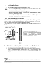
... in only one DDR3 memory module is recommended that memory of the same capacity, brand, speed, and chips be used . (Go to GIGABYTE's website for optimum performance. After the memory is installed, be sure to install it is installed. 2. Dual Channel mode cannot be enabled ...DS/SS - - The four DDR3 memory sockets are unable to insert the memory, switch the direction. 1-4-1 Dual Channel Memory Configuration This motherboard provides four DDR3 memory sockets and supports Dual Channel Technology. When enabling Dual Channel mode with two memory modules, be sure to install them ...
... in only one DDR3 memory module is recommended that memory of the same capacity, brand, speed, and chips be used . (Go to GIGABYTE's website for optimum performance. After the memory is installed, be sure to install it is installed. 2. Dual Channel mode cannot be enabled ...DS/SS - - The four DDR3 memory sockets are unable to insert the memory, switch the direction. 1-4-1 Dual Channel Memory Configuration This motherboard provides four DDR3 memory sockets and supports Dual Channel Technology. When enabling Dual Channel mode with two memory modules, be sure to install them ...
Manual
Page 17
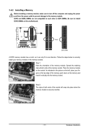
... place when the memory module is securely inserted. - 17 - Step 2: The clips at both ends of the memory socket. Place the memory module on this motherboard. 1-4-2 Installing a Memory Before installing a memory module, make sure to turn off the computer and unplug the power cord from the power outlet to prevent damage...
... place when the memory module is securely inserted. - 17 - Step 2: The clips at both ends of the memory socket. Place the memory module on this motherboard. 1-4-2 Installing a Memory Before installing a memory module, make sure to turn off the computer and unplug the power cord from the power outlet to prevent damage...

Manual
Page 18
Remove the metal slot cover from the power outlet before you begin to install an expansion card: • Make sure the motherboard supports the expansion card. Install the driver provided with your expansion card(s). 7. Secure the card's metal bracket to the chassis back panel with the slot, ...
Remove the metal slot cover from the power outlet before you begin to install an expansion card: • Make sure the motherboard supports the expansion card. Install the driver provided with your expansion card(s). 7. Secure the card's metal bracket to the chassis back panel with the slot, ...

Manual
Page 21
... 2/4/5.1/7.1-Channel Audio." • When removing the cable connected to connect center/subwoofer speakers in a 4/5.1/7.1-channel audio configuration. Do not rock it straight out from the motherboard. • When removing the cable, pull it side to side to 1 Gbps data rate.
... 2/4/5.1/7.1-Channel Audio." • When removing the cable connected to connect center/subwoofer speakers in a 4/5.1/7.1-channel audio configuration. Do not rock it straight out from the motherboard. • When removing the cable, pull it side to side to 1 Gbps data rate.
Manual
Page 22
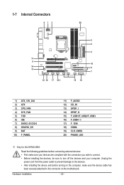
... devices and your devices are compliant with the connectors you wish to connect. • Before installing the devices, be sure to the connector on the motherboard. 1-7 Internal Connectors 413 20 11 9 14 13 12 18 17 16j 5 6 2 19 8 7 15 10 1) ATX_12V_2X4 2) ATX 3) CPU_FAN 4) SYS_FAN 5) FDD 6) IDE 7) SATA2_0/1/2/3/4 8) ...) CD_IN 13) SPDIF_I 14) SPDIF_O 15) F_USB1/F_USB2/F_USB3 16) F_USB4 j 17) F_1394 18) COMA 19) CLR_CMOS 20) PHASE_LED j Only for GA-H57M-USB3. Hardware Installation - 22 - Read the following guidelines before turning on the computer, make sure your computer.
... devices and your devices are compliant with the connectors you wish to connect. • Before installing the devices, be sure to the connector on the motherboard. 1-7 Internal Connectors 413 20 11 9 14 13 12 18 17 16j 5 6 2 19 8 7 15 10 1) ATX_12V_2X4 2) ATX 3) CPU_FAN 4) SYS_FAN 5) FDD 6) IDE 7) SATA2_0/1/2/3/4 8) ...) CD_IN 13) SPDIF_I 14) SPDIF_O 15) F_USB1/F_USB2/F_USB3 16) F_USB4 j 17) F_1394 18) COMA 19) CLR_CMOS 20) PHASE_LED j Only for GA-H57M-USB3. Hardware Installation - 22 - Read the following guidelines before turning on the computer, make sure your computer.

Manual
Page 23
... CPU manufacturer when using an Intel Extreme Edition CPU (130W). • To meet expansion requirements, it is turned off and all the components on the motherboard. If the 12V power connector is not connected, the computer will not start. • Use of the power connector, the power supply can lead to...
... CPU manufacturer when using an Intel Extreme Edition CPU (130W). • To meet expansion requirements, it is turned off and all the components on the motherboard. If the 12V power connector is not connected, the computer will not start. • Use of the power connector, the power supply can lead to...

Manual
Page 24
... disk drive. Overheating may hang. • These fan headers are : 360 KB, 720 KB, 1.2 MB, 1.44 MB, and 2.88 MB. The motherboard supports CPU fan speed control, which requires the use of the connector and the floppy disk drive cable. The pin 1 of the cable is recommended... on the headers. 5) FDD (Floppy Disk Drive Connector) This connector is the ground wire). The types of different color. 3/4) CPU_FAN/SYS_FAN (Fan Headers) The motherboard has a 4-pin CPU fan header (CPU_FAN) and a 4-pin (SYS_FAN). Before connecting a floppy disk drive, be sure to locate pin 1 of a CPU ...
... disk drive. Overheating may hang. • These fan headers are : 360 KB, 720 KB, 1.2 MB, 1.44 MB, and 2.88 MB. The motherboard supports CPU fan speed control, which requires the use of the connector and the floppy disk drive cable. The pin 1 of the cable is recommended... on the headers. 5) FDD (Floppy Disk Drive Connector) This connector is the ground wire). The types of different color. 3/4) CPU_FAN/SYS_FAN (Fan Headers) The motherboard has a 4-pin CPU fan header (CPU_FAN) and a 4-pin (SYS_FAN). Before connecting a floppy disk drive, be sure to locate pin 1 of a CPU ...

Manual
Page 28
.... For HD Front Panel Audio: For AC'97 Front Panel Audio: Pin No. Pin No. Incorrect connection between the module connector and the motherboard header will be present on each wire instead of a single plug. Definition Pin No. For information about connecting the front panel audio module that has ...
.... For HD Front Panel Audio: For AC'97 Front Panel Audio: Pin No. Pin No. Incorrect connection between the module connector and the motherboard header will be present on each wire instead of a single plug. Definition Pin No. For information about connecting the front panel audio module that has ...


