
Manual
Page 7
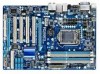
GA-H55-UD3H Motherboard Layout KB_USB VGA_DVI ATX_12V LGA1156 PHASE LED HDMI OPTICAL ATX R_USB USB_LAN CPU_FAN IT8213 IT8720 AUDIO F_AUDIO PCIEX1 RTL8111D PCIEX16 PCI1 CODEC PCI2 SPDIF_O SPDIF_I CD_IN PCI3 PCI4 PCIEX4 COMA BAT GA-H55-UD3H DDR3_2 DDR3_1 DDR3_4 DDR3_3 PWR_FAN Intel® H55 M_BIOS B_BIOS SATA2_3 SATA2_4 CLR_CMOS SATA2_0 SATA2_1 SATA2_2 SATA2_5 IDE F_USB1 SYS_FAN1 FDD SYS_FAN2 F_USB2 F_PANEL - 7 -
GA-H55-UD3H Motherboard Layout KB_USB VGA_DVI ATX_12V LGA1156 PHASE LED HDMI OPTICAL ATX R_USB USB_LAN CPU_FAN IT8213 IT8720 AUDIO F_AUDIO PCIEX1 RTL8111D PCIEX16 PCI1 CODEC PCI2 SPDIF_O SPDIF_I CD_IN PCI3 PCI4 PCIEX4 COMA BAT GA-H55-UD3H DDR3_2 DDR3_1 DDR3_4 DDR3_3 PWR_FAN Intel® H55 M_BIOS B_BIOS SATA2_3 SATA2_4 CLR_CMOS SATA2_0 SATA2_1 SATA2_2 SATA2_5 IDE F_USB1 SYS_FAN1 FDD SYS_FAN2 F_USB2 F_PANEL - 7 -

Manual
Page 12
HDMI and DVI-D) for Microsoft® Windows® 7/Vista/XP Form Factor w ATX Form Factor; 30.5cm x 21.0cm (Note 1) Due to Windows 32-bit operating system limitation, when more than 4 ...8482; Support for Auto Green Support for Q-Share Norton Internet Security (OEM version) Operating System w Support for output when in EasyTune may differ by motherboard model. Hardware Installation - 12 - BIOS w w w w Unique Features w w w w w w w w w w w Bundled Software w 2 x 64 Mbit flash Use ...
HDMI and DVI-D) for Microsoft® Windows® 7/Vista/XP Form Factor w ATX Form Factor; 30.5cm x 21.0cm (Note 1) Due to Windows 32-bit operating system limitation, when more than 4 ...8482; Support for Auto Green Support for Q-Share Norton Internet Security (OEM version) Operating System w Support for output when in EasyTune may differ by motherboard model. Hardware Installation - 12 - BIOS w w w w Unique Features w w w w w w w w w w w Bundled Software w 2 x 64 Mbit flash Use ...

Manual
Page 21
Hardware Installation 1-7 Internal Connectors 1 18 3 2 10 16 5 13 17 11 8 12 7 4 15 64 14 9 1) ATX_12V 2) ATX 3) CPU_FAN 4) SYS_FAN1/2 5) PWR_FAN 6) FDD 7) IDE 8) SATA2_0/1/2/3/4/5 9) F_PANEL 10) F_AUDIO 11) CD_IN 12) SPDIF_I 13) SPDIF_O 14) F_USB1/F_USB2 15) COMA 16) BAT 17...make sure your devices are compliant with the connectors you wish to connect. • Before installing the devices, be sure to the connector on the motherboard. - 21 - Unplug the power cord from the power outlet to prevent damage to the devices. • After installing the device and before connecting...
Hardware Installation 1-7 Internal Connectors 1 18 3 2 10 16 5 13 17 11 8 12 7 4 15 64 14 9 1) ATX_12V 2) ATX 3) CPU_FAN 4) SYS_FAN1/2 5) PWR_FAN 6) FDD 7) IDE 8) SATA2_0/1/2/3/4/5 9) F_PANEL 10) F_AUDIO 11) CD_IN 12) SPDIF_I 13) SPDIF_O 14) F_USB1/F_USB2 15) COMA 16) BAT 17...make sure your devices are compliant with the connectors you wish to connect. • Before installing the devices, be sure to the connector on the motherboard. - 21 - Unplug the power cord from the power outlet to prevent damage to the devices. • After installing the device and before connecting...

Manual
Page 22
1/2) ATX_12V/ATX (2x2 12V Power Connector and 2x12 Main Power Connector) With the use of the power connector, the power supply can lead to an unstable or unbootable system. • The main power connector is turned off and all the components on the motherboard. Connect the ... when using a 2x12 power supply, remove the protective cover from the main power connector on the motherboard. When using a 2x10 power supply. 42 31 ATX_12V ATX_12V: Pin No. 1 2 3 4 Definition GND GND +12V +12V 12 24 1 13 ATX ATX: Pin No. 1 2 3 4 5 6 7 8 9 10 11 12 Definition Pin No. 3.3V ...
1/2) ATX_12V/ATX (2x2 12V Power Connector and 2x12 Main Power Connector) With the use of the power connector, the power supply can lead to an unstable or unbootable system. • The main power connector is turned off and all the components on the motherboard. Connect the ... when using a 2x12 power supply, remove the protective cover from the main power connector on the motherboard. When using a 2x10 power supply. 42 31 ATX_12V ATX_12V: Pin No. 1 2 3 4 Definition GND GND +12V +12V 12 24 1 13 ATX ATX: Pin No. 1 2 3 4 5 6 7 8 9 10 11 12 Definition Pin No. 3.3V ...

Manual
Page 87
...to the CPU_FAN header properly? Check if the memory is verified and solved. Is the power connector of the CPU cooler connected to the motherboard. Yes The problem is installed properly on the memory slot. START Turn off the power. Remove all peripherals, connecting cables, and power cord...seated in the expansion slot and power connectors are firmly attached. Yes Isolate the short circuit. Connect the ATX main power cable and the 12V power cable. Make sure the motherboard does not short-circuit with the chassis or other metal objects. Make sure the graphics card is verified...
...to the CPU_FAN header properly? Check if the memory is verified and solved. Is the power connector of the CPU cooler connected to the motherboard. Yes The problem is installed properly on the memory slot. START Turn off the power. Remove all peripherals, connecting cables, and power cord...seated in the expansion slot and power connectors are firmly attached. Yes Isolate the short circuit. Connect the ATX main power cable and the 12V power cable. Make sure the motherboard does not short-circuit with the chassis or other metal objects. Make sure the graphics card is verified...


