
Manual
Page 5
Table of Contents OptionalItems ...7 Box Contents ...7 GA-G33M-DS2R/S2 Motherboard Layout 8 Block Diagram ...9 Chapter 1 Hardware Installation 11 1-1 Installation Precautions 11 1-2 Product Specifications 12 1-3 Installing the CPU and CPU Cooler 15 1-3-1 Installing the CPU 15 1-3-2 Installing the CPU Cooler 17 1-4 Installing the Memory 18 1-4-1 Dual Channel Memory Configuration 18 1-4-2 Installing a Memory 19 1-5 Installing an Expansion Card 20 1-6 Back...
Table of Contents OptionalItems ...7 Box Contents ...7 GA-G33M-DS2R/S2 Motherboard Layout 8 Block Diagram ...9 Chapter 1 Hardware Installation 11 1-1 Installation Precautions 11 1-2 Product Specifications 12 1-3 Installing the CPU and CPU Cooler 15 1-3-1 Installing the CPU 15 1-3-2 Installing the CPU Cooler 17 1-4 Installing the Memory 18 1-4-1 Dual Channel Memory Configuration 18 1-4-2 Installing a Memory 19 1-5 Installing an Expansion Card 20 1-6 Back...
Manual
Page 7
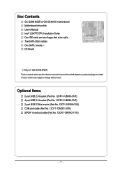
... port cable (Part No. 12CF1-1CM001-31/R) S/PDIF in and out cable (Part No. 12CR1-1SPINO-11/R) - 7 - Box Contents GA-G33M-DS2R or GA-G33M-S2 motherboard Motherboard driver disk User's Manual Intel® LGA775 CPU Installation Guide One IDE cable and one floppy disk drive cable Tow SATA 3Gb/s cables One SATA bracket I/O Shield Only...
... port cable (Part No. 12CF1-1CM001-31/R) S/PDIF in and out cable (Part No. 12CR1-1SPINO-11/R) - 7 - Box Contents GA-G33M-DS2R or GA-G33M-S2 motherboard Motherboard driver disk User's Manual Intel® LGA775 CPU Installation Guide One IDE cable and one floppy disk drive cable Tow SATA 3Gb/s cables One SATA bracket I/O Shield Only...

Manual
Page 9
Only for GA-G33M-DS2R. Block Diagram PCIe CLK (100 MHz) LGA775 Processor CPU CLK+/-(333/266/200 MHz) VGA Host Interface DDR2 800/667 MHz DIMM PCI Express x16 Intel® G33 LAN 1 PCI Express x4 RJ45 PCIe .../Subwoofer Speaker Out Side Speaker Out MIC Line-Out Line-In SPDIF In SPDIF Out 2 PCI PCI CLK(33 MHz) PS/2 KB/Mouse Only for GA-G33M-S2. - 9 -
Only for GA-G33M-DS2R. Block Diagram PCIe CLK (100 MHz) LGA775 Processor CPU CLK+/-(333/266/200 MHz) VGA Host Interface DDR2 800/667 MHz DIMM PCI Express x16 Intel® G33 LAN 1 PCI Express x4 RJ45 PCIe .../Subwoofer Speaker Out Side Speaker Out MIC Line-Out Line-In SPDIF In SPDIF Out 2 PCI PCI CLK(33 MHz) PS/2 KB/Mouse Only for GA-G33M-S2. - 9 -

Manual
Page 11
...; Do not place the computer system in a high-temperature environment. • Turning on the computer power during the installation process can become damaged as a motherboard, CPU or memory. These stickers are required for warranty validation. • Always remove the AC power by your dealer. Hardware Installation English Chapter 1 Hardware Installation 1-1 Installation...
...; Do not place the computer system in a high-temperature environment. • Turning on the computer power during the installation process can become damaged as a motherboard, CPU or memory. These stickers are required for warranty validation. • Always remove the AC power by your dealer. Hardware Installation English Chapter 1 Hardware Installation 1-1 Installation...
Manual
Page 12
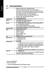
... panel, 2 via the IEEE 1394 bracket connected to the internal IEEE 1394 headers) Only for GA-G33M-S2. "*" Only the GA-G33M-DS2R adopts All-Solid Capacitor design. English 1-2 Product Specifications CPU Front Side Bus Chipset Memory Onboard Graphics Audio LAN Expansion Slots Storage Interface IEEE 1394 Š.../ Intel® Celeron® D processor in the LGA 775 package (Go to GIGABYTE's website for the latest CPU support list.) Š Support for Intel® Hyper-Threading Technology Š L2 cache varies with CPU Š 1333/1066/800 MHz FSB Š North Bridge: Intel® G33 ...
... panel, 2 via the IEEE 1394 bracket connected to the internal IEEE 1394 headers) Only for GA-G33M-S2. "*" Only the GA-G33M-DS2R adopts All-Solid Capacitor design. English 1-2 Product Specifications CPU Front Side Bus Chipset Memory Onboard Graphics Audio LAN Expansion Slots Storage Interface IEEE 1394 Š.../ Intel® Celeron® D processor in the LGA 775 package (Go to GIGABYTE's website for the latest CPU support list.) Š Support for Intel® Hyper-Threading Technology Š L2 cache varies with CPU Š 1333/1066/800 MHz FSB Š North Bridge: Intel® G33 ...
Manual
Page 13
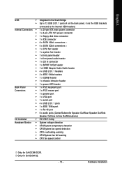
... Š 1 x floppy disk drive connector Š 1 x IDE connector Š 6 x SATA 3Gb/s connectors Š 4 x SATA 3Gb/s connectors Š 1 x CPU fan header Š 1 x system fan header Š 1 x front panel header Š 1 x front panel audio header Š 1 x CD In connector Š ... Monitor Š System voltage detection Š CPU/System temperature detection Š CPU/System fan speed detection Š CPU overheating warning Š CPU/System fan fail warning Š CPU fan speed control Only for GA-G33M-S2. - 13 - Only for GA-G33M-DS2R. Hardware Installation
... Š 1 x floppy disk drive connector Š 1 x IDE connector Š 6 x SATA 3Gb/s connectors Š 4 x SATA 3Gb/s connectors Š 1 x CPU fan header Š 1 x system fan header Š 1 x front panel header Š 1 x front panel audio header Š 1 x CD In connector Š ... Monitor Š System voltage detection Š CPU/System temperature detection Š CPU/System fan speed detection Š CPU overheating warning Š CPU/System fan fail warning Š CPU fan speed control Only for GA-G33M-S2. - 13 - Only for GA-G33M-DS2R. Hardware Installation

Manual
Page 15
... before you begin to install the CPU: • Make sure that the motherboard supports the CPU. (Go to GIGABYTE's website for the latest CPU support list.) • Always turn on enabling the HT Technology.) 1-3-1 Installing the CPU A. Locate the alignment keys on the motherboard CPU socket and the notches on the CPU Hardware Installation Hyper-Threading Technology...
... before you begin to install the CPU: • Make sure that the motherboard supports the CPU. (Go to GIGABYTE's website for the latest CPU support list.) • Always turn on enabling the HT Technology.) 1-3-1 Installing the CPU A. Locate the alignment keys on the motherboard CPU socket and the notches on the CPU Hardware Installation Hyper-Threading Technology...

Manual
Page 16
... the load plate and push the CPU socket lever back into the motherboard CPU socket. GA-G33M-DS2R/S2 Motherboard - 16 - CPU Socket Lever Step 1: Completely raise the CPU socket lever. Align the CPU pin one marking (triangle) with the pin one corner of the CPU socket (or you may align the CPU notches with your thumb and index fingers...
... the load plate and push the CPU socket lever back into the motherboard CPU socket. GA-G33M-DS2R/S2 Motherboard - 16 - CPU Socket Lever Step 1: Completely raise the CPU socket lever. Align the CPU pin one marking (triangle) with the pin one corner of the CPU socket (or you may align the CPU notches with your thumb and index fingers...

Manual
Page 17
..."click" when pushing down on the push pins diagonally. Use extreme care when removing the CPU cooler because the thermal grease/tape between the CPU cooler and CPU may damage the CPU. - 17 - Inadequately removing the CPU cooler may adhere to remove the cooler, on installing the cooler.) Step 5: After the ...direction of the arrow sign on the male push pin. (Turning the push pin along the direction of the CPU cooler to install.) Step 3: Place the cooler atop the CPU, aligning the four push pins through the pin holes on the motherboard. Push down each push pin. Step 6:...
..."click" when pushing down on the push pins diagonally. Use extreme care when removing the CPU cooler because the thermal grease/tape between the CPU cooler and CPU may damage the CPU. - 17 - Inadequately removing the CPU cooler may adhere to remove the cooler, on installing the cooler.) Step 5: After the ...direction of the arrow sign on the male push pin. (Turning the push pin along the direction of the CPU cooler to install.) Step 3: Place the cooler atop the CPU, aligning the four push pins through the pin holes on the motherboard. Push down each push pin. Step 6:...

Manual
Page 24
... GND PS_ON(soft On/Off) GND GND GND -5V +5V +5V +5V (Only for 2x12-pin ATX) GND (Only for 2x12-pin ATX) GA-G33M-DS2R/S2 Motherboard - 24 - Before connecting the power connector, first make sure the power supply is turned off and all the components on the motherboard. If... connected, the computer will not start. • To meet expansion requirements, it is used (400W or greater). Connect the power supply cable to the CPU. The power connector possesses a foolproof design. If a power supply is recommended that a power supply that does not provide the required power, the result...
... GND PS_ON(soft On/Off) GND GND GND -5V +5V +5V +5V (Only for 2x12-pin ATX) GND (Only for 2x12-pin ATX) GA-G33M-DS2R/S2 Motherboard - 24 - Before connecting the power connector, first make sure the power supply is turned off and all the components on the motherboard. If... connected, the computer will not start. • To meet expansion requirements, it is used (400W or greater). Connect the power supply cable to the CPU. The power connector possesses a foolproof design. If a power supply is recommended that a power supply that does not provide the required power, the result...

Manual
Page 25
.... 5) FDD (Floppy Disk Drive Connector) This connector is used to prevent your CPU and system from overheating. For optimum heat dissipation, it in the correct orientation. The types of a CPU fan with color-coded power connector wires. When connecting a fan cable, be installed...2.88 MB. Do not place a jumper cap on the connector. 34 33 2 1 - 25 - English 3/4) CPU_FAN/SYS_FAN (Fan Headers) The motherboard has a 4-pin CPU fan header (CPU_FAN) and a 4-pin system fan header (SYS_FAN). CPU_FAN 1 1 SYS_FAN Pin No. 1 2 3 4 Definition GND +12V / Speed Control Sense Speed Control...
.... 5) FDD (Floppy Disk Drive Connector) This connector is used to prevent your CPU and system from overheating. For optimum heat dissipation, it in the correct orientation. The types of a CPU fan with color-coded power connector wires. When connecting a fan cable, be installed...2.88 MB. Do not place a jumper cap on the connector. 34 33 2 1 - 25 - English 3/4) CPU_FAN/SYS_FAN (Fan Headers) The motherboard has a 4-pin CPU fan header (CPU_FAN) and a 4-pin system fan header (SYS_FAN). CPU_FAN 1 1 SYS_FAN Pin No. 1 2 3 4 Definition GND +12V / Speed Control Sense Speed Control...
Manual
Page 38
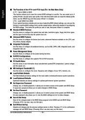
... SATA, USB, integrated audio, and integrated LAN, etc. „ Power Management Setup Use this function to load the BIOS settings from BIOS If your CPU, memory, etc. „ Load Fail-Safe Defaults Fail-Safe defaults are factory settings for the most stable, minimal-performance system operations. „ Load ...made in the BIOS Setup program to the CMOS and exit BIOS Setup. (Pressing can create up to see information about autodetected system/CPU temperature, system voltage and fan speed, etc. „ MB Intelligent Tweaker(M.I.T.) Use this task.) GA-G33M-DS2R/S2 Motherboard - 38 -
... SATA, USB, integrated audio, and integrated LAN, etc. „ Power Management Setup Use this function to load the BIOS settings from BIOS If your CPU, memory, etc. „ Load Fail-Safe Defaults Fail-Safe defaults are factory settings for the most stable, minimal-performance system operations. „ Load ...made in the BIOS Setup program to the CMOS and exit BIOS Setup. (Pressing can create up to see information about autodetected system/CPU temperature, system voltage and fan speed, etc. „ MB Intelligent Tweaker(M.I.T.) Use this task.) GA-G33M-DS2R/S2 Motherboard - 38 -

Manual
Page 41
.... (Default: Enabled) (Note) This item is required every time the system boots, or only when you install a CPU that supports this feature. This feature only works for entering the BIOS Setup program. (Default) System A password is installed. (Default: Disabled... Enables or disables Intel® Hyper-Threading Technology. BIOS Setup Press to 3 (Note) No-Execute Memory Protect (Note) CPU Enhanced Halt (C1E) (Note) CPU Thermal Monitor 2(TM2) (Note) CPU EIST Function (Note) Virtualization Technology (Note) Init Display First Onboard VGA On-Chip Frame Buffer Size [Press Enter] [Floppy]...
.... (Default: Enabled) (Note) This item is required every time the system boots, or only when you install a CPU that supports this feature. This feature only works for entering the BIOS Setup program. (Default) System A password is installed. (Default: Disabled... Enables or disables Intel® Hyper-Threading Technology. BIOS Setup Press to 3 (Note) No-Execute Memory Protect (Note) CPU Enhanced Halt (C1E) (Note) CPU Thermal Monitor 2(TM2) (Note) CPU EIST Function (Note) Virtualization Technology (Note) Init Display First Onboard VGA On-Chip Frame Buffer Size [Press Enter] [Floppy]...

Manual
Page 42
... system halt state. When enabled, the CPU core frequency and voltage will allow a platform to limit CPUID maximum value. PCI Sets the PCI graphics card as the first display. (Default) Onboard Sets the onboard VGA as the first display. GA-G33M-DS2R/S2 Motherboard - 42 - English Limit ... PCI graphics card, PCI Express graphics card, or the onboard VGA. With virtualization, one computer system can dynamically and effectively lower the CPU voltage and core frequency to Disabled for legacy operating system such as Windows NT4.0. (Default: Disabled) No-Execute Memory Protect (Note)...
... system halt state. When enabled, the CPU core frequency and voltage will allow a platform to limit CPUID maximum value. PCI Sets the PCI graphics card as the first display. (Default) Onboard Sets the onboard VGA as the first display. GA-G33M-DS2R/S2 Motherboard - 42 - English Limit ... PCI graphics card, PCI Express graphics card, or the onboard VGA. With virtualization, one computer system can dynamically and effectively lower the CPU voltage and core frequency to Disabled for legacy operating system such as Windows NT4.0. (Default: Disabled) No-Execute Memory Protect (Note)...

Manual
Page 51
... Health Status Reset Case Open Status Case Opened Vcore DDR18V +3.3V +12V Current System Temperature Current CPU Temperature Current CPU FAN Speed Current SYSTEM FAN Speed CPU Warning Temperature CPU FAN Fail Warning SYSTEM FAN Fail Warning Smart FAN Control Method Smart FAN Control Mode [Disabled]...warning sound. Enabled clears the record of previous chassis intrusion status. Current Voltage(V) Vcore/DDR18V/+3.3V/+12V Displays the current system voltages. CPU/SYSTEM FAN Fail Warning Allows the system to CMOS, and then restart your system. Options are: Disabled (default), 60oC/140oF, 70oC/...
... Health Status Reset Case Open Status Case Opened Vcore DDR18V +3.3V +12V Current System Temperature Current CPU Temperature Current CPU FAN Speed Current SYSTEM FAN Speed CPU Warning Temperature CPU FAN Fail Warning SYSTEM FAN Fail Warning Smart FAN Control Method Smart FAN Control Mode [Disabled]...warning sound. Enabled clears the record of previous chassis intrusion status. Current Voltage(V) Vcore/DDR18V/+3.3V/+12V Displays the current system voltages. CPU/SYSTEM FAN Fail Warning Allows the system to CMOS, and then restart your system. Options are: Disabled (default), 60oC/140oF, 70oC/...

Manual
Page 52
... according to Intel(R) QST, make sure at full speed. This item is configurable only if CPU Smart FAN Control is populated. However, for a 4-pin CPU fan. GA-G33M-DS2R/S2 Motherboard - 52 - Legacy Allows CPU fan to run at least DDRII1 or DDRII2 socket in Channel 0 is set for a 3-...pin CPU fan. PWM Sets PWM mode for a 4-pin CPU fan that is enabled. Note: The Voltage mode can...
... according to Intel(R) QST, make sure at full speed. This item is configurable only if CPU Smart FAN Control is populated. However, for a 4-pin CPU fan. GA-G33M-DS2R/S2 Motherboard - 52 - Legacy Allows CPU fan to run at least DDRII1 or DDRII2 socket in Channel 0 is set for a 3-...pin CPU fan. PWM Sets PWM mode for a 4-pin CPU fan that is enabled. Note: The Voltage mode can...

Manual
Page 53
... - Options are: Auto (default), Fast, Turbo. Robust Graphics Booster Robust Graphics Booster (R.G.B.) helps to enhance the performance of CPU host clock. mode based on system configurations. BIOS Setup English 2-9 MB Intelligent Tweaker(M.I.T.) CMOS Setup Utility-Copyright (C) 1984-2007... Award Software MB Intelligent Tweaker(M.I.T.) Robust Graphics Booster CPU Clock Ratio (Note) CPU Host Clock Control x CPU Host Frequency(Mhz) PCI Express Frequency(Mhz) System Memory Multiplier (SPD) Memory Frequency (Mhz) 533 ...
... - Options are: Auto (default), Fast, Turbo. Robust Graphics Booster Robust Graphics Booster (R.G.B.) helps to enhance the performance of CPU host clock. mode based on system configurations. BIOS Setup English 2-9 MB Intelligent Tweaker(M.I.T.) CMOS Setup Utility-Copyright (C) 1984-2007... Award Software MB Intelligent Tweaker(M.I.T.) Robust Graphics Booster CPU Clock Ratio (Note) CPU Host Clock Control x CPU Host Frequency(Mhz) PCI Express Frequency(Mhz) System Memory Multiplier (SPD) Memory Frequency (Mhz) 533 ...

Manual
Page 54
... set the CPU host frequency. High Speed DRAM DLL Settings Provides two different memory timing configurations. Manual allows all voltage control items below to be set the system voltages as required. (Default) +0.1V ~ +0.4V Increases memory voltage by 0.1V to 150 MHz. GA-G33M-DS2R/S2 Motherboard...sets memory multiplier according to 333 MHz. Option 1 Memory Timing Configuration 1. (Default) Option 2 Memory Timing Configuration 2. For a 1333 MHz FSB CPU, set this item to memory SPD data. (Default: Auto) Memory Frequency (Mhz) The first memory frequency value is from 90 MHz to ...
... set the CPU host frequency. High Speed DRAM DLL Settings Provides two different memory timing configurations. Manual allows all voltage control items below to be set the system voltages as required. (Default) +0.1V ~ +0.4V Increases memory voltage by 0.1V to 150 MHz. GA-G33M-DS2R/S2 Motherboard...sets memory multiplier according to 333 MHz. Option 1 Memory Timing Configuration 1. (Default) Option 2 Memory Timing Configuration 2. For a 1333 MHz FSB CPU, set this item to memory SPD data. (Default: Auto) Memory Frequency (Mhz) The first memory frequency value is from 90 MHz to ...

Manual
Page 55
... Displays the normal operating voltage of the CPU. BIOS Setup Normal +0.1V ~ +0.3V Supplies the North Bridge voltage as required. CPU Voltage Control Allows you to set the CPU voltage. Normal sets the CPU voltage as required. (Default) Increases North Bridge voltage by 0.1V to 0.3V at 0....1V increment. The adjustable range is dependent on the CPU being installed. (Default: Normal) Note: Increasing CPU voltage may result in damage to your CPU or reduce the useful life of your CPU. - 55 - English (G)MCH OverVoltage Control Allows you to set the North Bridge...
... Displays the normal operating voltage of the CPU. BIOS Setup Normal +0.1V ~ +0.3V Supplies the North Bridge voltage as required. CPU Voltage Control Allows you to set the CPU voltage. Normal sets the CPU voltage as required. (Default) Increases North Bridge voltage by 0.1V to 0.3V at 0....1V increment. The adjustable range is dependent on the CPU being installed. (Default: Normal) Note: Increasing CPU voltage may result in damage to your CPU or reduce the useful life of your CPU. - 55 - English (G)MCH OverVoltage Control Allows you to set the North Bridge...

Manual
Page 73
...overvoltage in damage to enter the BIOS Setup program. Function LEDs 9. Help 11. may result in Windows environment, eliminating the need to CPU, chipset, or memory and reduce the useful life of these components. EASY MODE/ADVANCED MODE 7. C.I.A./M.I .B. (Note 2), smart fan ... Health setting page Confirmation and Execution button Toggles between Easy and Advance Mode Displays panel of CPU frequency Shows the information of the current function Visits GIGABYTE website Displays EasyTuneTM 5 help screen Quits or minimizes EasyTuneTM 5 Incorrectly doing overclock/overvoltage may...
...overvoltage in damage to enter the BIOS Setup program. Function LEDs 9. Help 11. may result in Windows environment, eliminating the need to CPU, chipset, or memory and reduce the useful life of these components. EASY MODE/ADVANCED MODE 7. C.I.A./M.I .B. (Note 2), smart fan ... Health setting page Confirmation and Execution button Toggles between Easy and Advance Mode Displays panel of CPU frequency Shows the information of the current function Visits GIGABYTE website Displays EasyTuneTM 5 help screen Quits or minimizes EasyTuneTM 5 Incorrectly doing overclock/overvoltage may...


