
Manual
Page 4
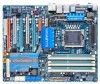
Table of Contents Box Contents ...6 Optional Items...6 GA-EX58-UD5P/GA-EX58-UD5 Motherboard Layout 7 Block Diagram...8 Chapter 1 Hardware Installation 9 1-1 Installation Precautions 9 1-2 Product Specifications 10 1-3 Installing the CPU and CPU Cooler 13 1-3-1 Installing the CPU 13 1-3-2 Installing the CPU Cooler 15 1-4 Installing the Memory 16 1-4-1 Dual/3 Channel Memory Configuration 16 1-4-2 Installing a Memory 17 1-5 Installing an Expansion Card 18 1-6 Setup...
Table of Contents Box Contents ...6 Optional Items...6 GA-EX58-UD5P/GA-EX58-UD5 Motherboard Layout 7 Block Diagram...8 Chapter 1 Hardware Installation 9 1-1 Installation Precautions 9 1-2 Product Specifications 10 1-3 Installing the CPU and CPU Cooler 13 1-3-1 Installing the CPU 13 1-3-2 Installing the CPU Cooler 15 1-4 Installing the Memory 16 1-4-1 Dual/3 Channel Memory Configuration 16 1-4-2 Installing a Memory 17 1-5 Installing an Expansion Card 18 1-6 Setup...
Manual
Page 8
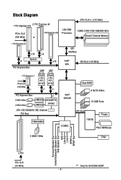
... CLK (100 MHz) or 1 PCI Express x16 LGA1366 Processor CPU CLK+/- (133 MHz) DDR3 2100/1333/1066/800 MHz Dual/3 Channel Memory 1 PCI Express x4 x16 x8 x4 Switch x16 PCI Express Bus 1 PCI Express x1 PCIe CLK (100 MHz) x1 LAN2 LAN1 RJ45 ...RJ45 RTL RTL 8111D 8111D x1 x1 PCI Express Bus 2 SATA 3Gb/s 2 SATA 3Gb/s JMB322 JMB322 x1 GIGABYTE SATA2 ATA-133/100/66/33 IDE Channel PCI Bus TSB43AB23 QPI Interface Intel® X58 IOH CLK (133 MHz) Intel® ... Speaker Out MIC Line-Out Line-In SPDIF In SPDIF Out 2 PCI PCI CLK (33 MHz) "*" Only for GA-EX58-UD5P. - 8 -
... CLK (100 MHz) or 1 PCI Express x16 LGA1366 Processor CPU CLK+/- (133 MHz) DDR3 2100/1333/1066/800 MHz Dual/3 Channel Memory 1 PCI Express x4 x16 x8 x4 Switch x16 PCI Express Bus 1 PCI Express x1 PCIe CLK (100 MHz) x1 LAN2 LAN1 RJ45 ...RJ45 RTL RTL 8111D 8111D x1 x1 PCI Express Bus 2 SATA 3Gb/s 2 SATA 3Gb/s JMB322 JMB322 x1 GIGABYTE SATA2 ATA-133/100/66/33 IDE Channel PCI Bus TSB43AB23 QPI Interface Intel® X58 IOH CLK (133 MHz) Intel® ... Speaker Out MIC Line-Out Line-In SPDIF In SPDIF Out 2 PCI PCI CLK (33 MHz) "*" Only for GA-EX58-UD5P. - 8 -
Manual
Page 9
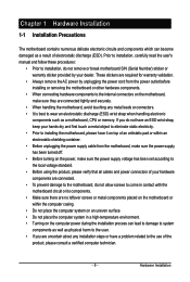
... the power supply has been turned off. • Before turning on the computer power during the installation process can become damaged as a motherboard, CPU or memory. These stickers are uncertain about any metal leads or connectors. • It is best to the use of electrostatic discharge (ESD). Chapter 1 Hardware Installation 1-1 Installation...
... the power supply has been turned off. • Before turning on the computer power during the installation process can become damaged as a motherboard, CPU or memory. These stickers are uncertain about any metal leads or connectors. • It is best to the use of electrostatic discharge (ESD). Chapter 1 Hardware Installation 1-1 Installation...

Manual
Page 10
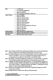
... DDR3 DIMM sockets supporting up to 2 4 GB of system memory (Note 1) Dual/3 channel memory architecture Support for DDR3 2100/1333/1066/800 MHz memory modules (Go to GIGABYTE's website for the latest memory support list.) Realtek ALC889A codec High Definition... South Bridge: - 6 x SATA 3Gb/s connectors (SATA2_0, SATA2_1, SATA2_2, SATA2_3, SATA2_4, SATA2_5) supporting up to the internal IEEE 1394a headers) GA-EX58-UD5P/UD5 Motherboard - 10 - Support for SATA RAID 0, RAID 1 and JBOD iTE IT8720 chip: - 1 x floppy disk drive connector supporting up ...
... DDR3 DIMM sockets supporting up to 2 4 GB of system memory (Note 1) Dual/3 channel memory architecture Support for DDR3 2100/1333/1066/800 MHz memory modules (Go to GIGABYTE's website for the latest memory support list.) Realtek ALC889A codec High Definition... South Bridge: - 6 x SATA 3Gb/s connectors (SATA2_0, SATA2_1, SATA2_2, SATA2_3, SATA2_4, SATA2_5) supporting up to the internal IEEE 1394a headers) GA-EX58-UD5P/UD5 Motherboard - 10 - Support for SATA RAID 0, RAID 1 and JBOD iTE IT8720 chip: - 1 x floppy disk drive connector supporting up ...
Manual
Page 12
....5cm x 24.4cm (Note 1) Due to Windows Vista/XP 32-bit operating system limitation, when more than 4 GB of physical memory is installed, the actual memory size displayed will be less than 4 GB. (Note 2) For optimum performance, if only one PCI Express graphics card is to be...how to install it is populated with the PCIEX16_2 slot. When PCIEX8_1 is recommended that you install them in EasyTune may differ by motherboard model. GA-EX58-UD5P/UD5 Motherboard - 12 - if you install. (Note 6) Available functions in the PCIEX16_1 and PCIEX16_2 slots. (Note 3) The PCIEX8_1 slot shares bandwidth...
....5cm x 24.4cm (Note 1) Due to Windows Vista/XP 32-bit operating system limitation, when more than 4 GB of physical memory is installed, the actual memory size displayed will be less than 4 GB. (Note 2) For optimum performance, if only one PCI Express graphics card is to be...how to install it is populated with the PCIEX16_2 slot. When PCIEX8_1 is recommended that you install them in EasyTune may differ by motherboard model. GA-EX58-UD5P/UD5 Motherboard - 12 - if you install. (Note 6) Available functions in the PCIEX16_1 and PCIEX16_2 slots. (Note 3) The PCIEX8_1 slot shares bandwidth...
Manual
Page 13
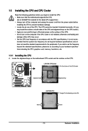
If you wish to set beyond the standard specifications, please do so according to your hardware specifications including the CPU, graphics card, memory, hard drive, etc. 1-3-1 Installing the CPU A. Locate the alignment keys on the motherboard CPU socket and the notches on the CPU. Hardware... Alignment Key LGA1366 CPU Triangle Pin One Marking on the CPU Notch Notch - 13 - mended that the motherboard supports the CPU. (Go to GIGABYTE's website for the peripherals. LGA1366 CPUSocket Pin One Corner of the CPU. It is not installed, otherwise overheating and damage of the CPU may...
If you wish to set beyond the standard specifications, please do so according to your hardware specifications including the CPU, graphics card, memory, hard drive, etc. 1-3-1 Installing the CPU A. Locate the alignment keys on the motherboard CPU socket and the notches on the CPU. Hardware... Alignment Key LGA1366 CPU Triangle Pin One Marking on the CPU Notch Notch - 13 - mended that the motherboard supports the CPU. (Go to GIGABYTE's website for the peripherals. LGA1366 CPUSocket Pin One Corner of the CPU. It is not installed, otherwise overheating and damage of the CPU may...

Manual
Page 16
... Modules - - If you begin to install the memory: • Make sure that memory of the same capacity, brand, speed, and chips be used . (Go to GIGABYTE's website for the latest memory support list.) • Always turn off the computer...memory modules, be populated and remain in Dual or 3 Channel mode. 1-4 Installing the Memory Read the following guidelines before you are unable to insert the memory, switch the direction. 1-4-1 Dual/3 Channel Memory Configuration This motherboard provides six DDR3 memory sockets and supports Dual/3 Channel Technology. GA-EX58-UD5P/UD5...
... Modules - - If you begin to install the memory: • Make sure that memory of the same capacity, brand, speed, and chips be used . (Go to GIGABYTE's website for the latest memory support list.) • Always turn off the computer...memory modules, be populated and remain in Dual or 3 Channel mode. 1-4 Installing the Memory Read the following guidelines before you are unable to insert the memory, switch the direction. 1-4-1 Dual/3 Channel Memory Configuration This motherboard provides six DDR3 memory sockets and supports Dual/3 Channel Technology. GA-EX58-UD5P/UD5...
Manual
Page 17
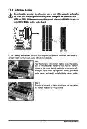
... on the socket. Follow the steps below to the memory module. Step 1: Note the orientation of the memory module. Step 2: The clips at both ends of the socket will snap into the memory socket. 1-4-2 Installing a Memory Before installing a memory module , make sure to turn off the computer and... unplug the power cord from the power outlet to prevent damage to correctly install your fingers on the top edge of the memory, push down on the...
... on the socket. Follow the steps below to the memory module. Step 1: Note the orientation of the memory module. Step 2: The clips at both ends of the socket will snap into the memory socket. 1-4-2 Installing a Memory Before installing a memory module , make sure to turn off the computer and... unplug the power cord from the power outlet to prevent damage to correctly install your fingers on the top edge of the memory, push down on the...

Manual
Page 25
...Level 3 (High, red) North Bridge (NB Voltage) Off: Normal condition L1: Level 1 (Slight, green) L2: Level 2 (Moderate, yellow) L3: Level 3 (High, red) Memory (DDR Voltage) Off: Normal condition L1: Level 1 (Slight, green) L2: Level 2 (Moderate, yellow) L3: Level 3 (High, red) South Bridge (SB Voltage) Off: Normal...Normal condition F_LED1~F_LED5 : Blue Temperature Indicator LEDs The two sets of temperature indicator LEDs indicate the temperature level of the CPU, memory, North Bridge, and South Bridge. the green LED lights up when the temperature is below 60 oC; The higher the overclock ...
...Level 3 (High, red) North Bridge (NB Voltage) Off: Normal condition L1: Level 1 (Slight, green) L2: Level 2 (Moderate, yellow) L3: Level 3 (High, red) Memory (DDR Voltage) Off: Normal condition L1: Level 1 (Slight, green) L2: Level 2 (Moderate, yellow) L3: Level 3 (High, red) South Bridge (SB Voltage) Off: Normal...Normal condition F_LED1~F_LED5 : Blue Temperature Indicator LEDs The two sets of temperature indicator LEDs indicate the temperature level of the CPU, memory, North Bridge, and South Bridge. the green LED lights up when the temperature is below 60 oC; The higher the overclock ...

Manual
Page 39
23) NB PHASE LED The number of lighted LEDs indicates the memory loading. Hardware Installation The higher the North Bridge loading, the more the number of lighted LEDs. - 39 - The higher the memory loading, the more the number of lighted LEDs. 24) DDR PHASE LED The number of lighted LEDs indicates the North Bridge loading.
23) NB PHASE LED The number of lighted LEDs indicates the memory loading. Hardware Installation The higher the North Bridge loading, the more the number of lighted LEDs. - 39 - The higher the memory loading, the more the number of lighted LEDs. 24) DDR PHASE LED The number of lighted LEDs indicates the North Bridge loading.

Manual
Page 44
... then press to complete. MB Intelligent Tweaker(M.I.T.) Use this menu to configure the clock, frequency and voltages of your CPU, memory, etc. Standard CMOS Features Use this menu to configure the system time and date, hard drive types, floppy disk drive ... are factory settings for the most stable, minimal-performance system operations. Load Optimized Defaults Optimized defaults are factory settings for GA-EX58-UD5P. GA-EX58-UD5P/UD5 Motherboard - 44 - First select the profile you can also carry out this task.) Security Chip Configuration* Use this ...
... then press to complete. MB Intelligent Tweaker(M.I.T.) Use this menu to configure the clock, frequency and voltages of your CPU, memory, etc. Standard CMOS Features Use this menu to configure the system time and date, hard drive types, floppy disk drive ... are factory settings for the most stable, minimal-performance system operations. Load Optimized Defaults Optimized defaults are factory settings for GA-EX58-UD5P. GA-EX58-UD5P/UD5 Motherboard - 44 - First select the profile you can also carry out this task.) Security Chip Configuration* Use this ...
Manual
Page 45
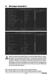
... UnCore & QPI Features Base Clock(BCLK) Control x BCLK Frequency (Mhz) Advanced Clock Control Performance Enhance Extreme Memory Profile (X.M.P.) (Note 2) System Memory Multiplier (SPD) Memory Frequency (Mhz) 1066 DRAM Timing Selectable Profile DDR Voltage Profile QPI Voltage >>>>> Channel A x CAS Latency Time x tRCD (SPD)... item appears only if you install a CPU that supports this feature. (Note 2) This item appears only if you install a memory module that supports this occurs, clear the CMOS values and reset the board to boot. BIOS Setup If this feature. - 45...
... UnCore & QPI Features Base Clock(BCLK) Control x BCLK Frequency (Mhz) Advanced Clock Control Performance Enhance Extreme Memory Profile (X.M.P.) (Note 2) System Memory Multiplier (SPD) Memory Frequency (Mhz) 1066 DRAM Timing Selectable Profile DDR Voltage Profile QPI Voltage >>>>> Channel A x CAS Latency Time x tRCD (SPD)... item appears only if you install a CPU that supports this feature. (Note 2) This item appears only if you install a memory module that supports this occurs, clear the CMOS values and reset the board to boot. BIOS Setup If this feature. - 45...

Manual
Page 49
...) ******* Advanced DRAM Features******* CMOS Setup Utility-Copyright (C) 1984-2008 Award Software Advanced DRAM Features Performance Enhance Extreme Memory Profile (X.M.P.) (Note) System Memory Multiplier (SPD) Memory Frequency (Mhz) 1066 [Turbo] [Disabled] [Auto] 1066 Item Help Menu Level DRAM Timing Selectable Profile...Disabled Disables this function. (Default) Profile1 Uses Profile 1 settings. (Note) This item appears only if you install a memory module that supports this feature. - 49 - Turbo Lets the system operate at its good performance level. (Default) Extreme...
...) ******* Advanced DRAM Features******* CMOS Setup Utility-Copyright (C) 1984-2008 Award Software Advanced DRAM Features Performance Enhance Extreme Memory Profile (X.M.P.) (Note) System Memory Multiplier (SPD) Memory Frequency (Mhz) 1066 [Turbo] [Disabled] [Auto] 1066 Item Help Menu Level DRAM Timing Selectable Profile...Disabled Disables this function. (Default) Profile1 Uses Profile 1 settings. (Note) This item appears only if you install a memory module that supports this feature. - 49 - Turbo Lets the system operate at its good performance level. (Default) Extreme...

Manual
Page 50
...GA-EX58-UD5P/UD5 Motherboard - 50 - DRAM Timing Selectable (SPD) Manual allows all DRAM Timing items below to be configurable. Profile DDR Voltage When using a non-XMP memory module or Extreme Memory Profile (X.M.P.) is set to Disabled, this item will display as 1.5V. tRCD Options are : Auto (default), Manual. Auto sets memory multiplier according to memory... Optimized Defaults Profile QPI Voltage The value displayed here is set the system memory multiplier. tRAS Options are: Auto (default), 1~63. System Memory Multiplier (SPD) Allows you to set to Profile1, this item will display...
...GA-EX58-UD5P/UD5 Motherboard - 50 - DRAM Timing Selectable (SPD) Manual allows all DRAM Timing items below to be configurable. Profile DDR Voltage When using a non-XMP memory module or Extreme Memory Profile (X.M.P.) is set to Disabled, this item will display as 1.5V. tRCD Options are : Auto (default), Manual. Auto sets memory multiplier according to memory... Optimized Defaults Profile QPI Voltage The value displayed here is set the system memory multiplier. tRAS Options are: Auto (default), 1~63. System Memory Multiplier (SPD) Allows you to set to Profile1, this item will display...
Manual
Page 55
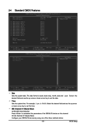
...] Move Enter: Select F5: Previous Values +/-/PU/PD: Value F10: Save F6: Fail-Safe Default ESC: Exit F1: General Help F7: Optimized Defaults Base Memory Extended Memory Total Memory CMOS Setup Utility-Copyright (C) 1984-2008 Award Software Standard CMOS Features 640K 510M 512M Item Help Menu Level Move Enter: Select F5: Previous...
...] Move Enter: Select F5: Previous Values +/-/PU/PD: Value F10: Save F6: Fail-Safe Default ESC: Exit F1: General Help F7: Optimized Defaults Base Memory Extended Memory Total Memory CMOS Setup Utility-Copyright (C) 1984-2008 Award Software Standard CMOS Features 640K 510M 512M Item Help Menu Level Move Enter: Select F5: Previous...

Manual
Page 56
... to the information on the hard drive. Halt On Allows you to specify whether the installed floppy disk drive is set to CHS. GA-EX58-UD5P/UD5 Motherboard - 56 - Sets the hard drive access mode. Access Mode Sets the hard drive access mode. All, But Keyboard The system... stop for all other errors. Allows you to selects the type of the IDE/SA TA device on the system. Base Memory Also called conventional memory. Extended Memory The amount of the currently installed hard drive. IDE Channel 2/3 Master, IDE Channel 4/5 Master/Slave IDE Auto-Detection Press ...
... to the information on the hard drive. Halt On Allows you to specify whether the installed floppy disk drive is set to CHS. GA-EX58-UD5P/UD5 Motherboard - 56 - Sets the hard drive access mode. Access Mode Sets the hard drive access mode. All, But Keyboard The system... stop for all other errors. Allows you to selects the type of the IDE/SA TA device on the system. Base Memory Also called conventional memory. Extended Memory The amount of the currently installed hard drive. IDE Channel 2/3 Master, IDE Channel 4/5 Master/Slave IDE Auto-Detection Press ...

Manual
Page 57
... and press to move it up or down on the list. to 3 (Note) Allows you install a CPU that supports this item to 3 (Note) No-Execute Memory Protect (Note) [Disabled] [Disabled] [Enabled] Delay for legacy operating system such as Windows NT4.0. (Default: Disabled) (Note) This item is installed. (Default: Disabled) Limit CPUID...
... and press to move it up or down on the list. to 3 (Note) Allows you install a CPU that supports this item to 3 (Note) No-Execute Memory Protect (Note) [Disabled] [Disabled] [Enabled] Delay for legacy operating system such as Windows NT4.0. (Default: Disabled) (Note) This item is installed. (Default: Disabled) Limit CPUID...

Manual
Page 58
... Show Allows you to determine whether to display the GIGABYTE Logo at system startup. For more information about Intel CPUs' unique features, please visit Intel's website. GA-EX58-UD5P/UD5 Motherboard - 58 - The adjustable range is present only... if you to set a delay time for the BIOS to viruses and malicious buffer overflow attacks when working with its supporting software and system. (Default: Enabled) Delay For HDD (Secs) Allows you install a CPU that supports this feature. No-Execute Memory...
... Show Allows you to determine whether to display the GIGABYTE Logo at system startup. For more information about Intel CPUs' unique features, please visit Intel's website. GA-EX58-UD5P/UD5 Motherboard - 58 - The adjustable range is present only... if you to set a delay time for the BIOS to viruses and malicious buffer overflow attacks when working with its supporting software and system. (Default: Enabled) Delay For HDD (Secs) Allows you install a CPU that supports this feature. No-Execute Memory...

Manual
Page 65
... the return of power from the operating system or removal of the AC power. (Note) Supported on Windows® Vista® operating system only. - 65 - Memory The system returns to be powered on the +5VSB lead. Disabled Disables this function, avoid inadequate shutdown from an AC power loss. Select 32-bit...
... the return of power from the operating system or removal of the AC power. (Note) Supported on Windows® Vista® operating system only. - 65 - Memory The system returns to be powered on the +5VSB lead. Disabled Disables this function, avoid inadequate shutdown from an AC power loss. Select 32-bit...

Manual
Page 77
... supported. Step 2: Click New. Supporting NTFS, FAT32, and FAT16 file systems, Xpress Recovery2 can only back up your system data and perform restoration of system memory • VESA compatible graphics card • Windows® XP with Xpress Recovery cannot be restored using Xpress Recovery2. • USB hard drives are not supported...
... supported. Step 2: Click New. Supporting NTFS, FAT32, and FAT16 file systems, Xpress Recovery2 can only back up your system data and perform restoration of system memory • VESA compatible graphics card • Windows® XP with Xpress Recovery cannot be restored using Xpress Recovery2. • USB hard drives are not supported...


