Manual
Page 1
GA-EX58-UD5P/ GA-EX58-UD5 LGA1366 socket motherboard for Intel® CoreTM i7 processor family User's Manual Rev. 1005 12ME-EX58UD5-1005R
GA-EX58-UD5P/ GA-EX58-UD5 LGA1366 socket motherboard for Intel® CoreTM i7 processor family User's Manual Rev. 1005 12ME-EX58UD5-1005R

Manual
Page 2
Motherboard GA-EX58-UD5P/GA-EX58-UD5 Oct. 31, 2008 Motherboard GA-EX58-UD5P/ GA-EX58-UD5 Oct. 31, 2008
Motherboard GA-EX58-UD5P/GA-EX58-UD5 Oct. 31, 2008 Motherboard GA-EX58-UD5P/ GA-EX58-UD5 Oct. 31, 2008

Manual
Page 4
Table of Contents Box Contents ...6 Optional Items...6 GA-EX58-UD5P/GA-EX58-UD5 Motherboard Layout 7 Block Diagram...8 Chapter 1 Hardware Installation 9 1-1 Installation Precautions 9 1-2 Product Specifications 10 1-3 Installing the CPU and CPU Cooler 13 1-3-1 Installing the CPU 13 1-3-2 Installing the ...
Table of Contents Box Contents ...6 Optional Items...6 GA-EX58-UD5P/GA-EX58-UD5 Motherboard Layout 7 Block Diagram...8 Chapter 1 Hardware Installation 9 1-1 Installation Precautions 9 1-2 Product Specifications 10 1-3 Installing the CPU and CPU Cooler 13 1-3-1 Installing the CPU 13 1-3-2 Installing the ...

Manual
Page 6
Box Contents GA-EX58-UD5P/GA-EX58-UD5 motherboard Motherboard driver disk User's Manual Quick Installation Guide One IDE cable Four SATA 3Gb/s cables One SATA bracket I/O shield 2-Way SLI bridge connector 3-Way ...
Box Contents GA-EX58-UD5P/GA-EX58-UD5 motherboard Motherboard driver disk User's Manual Quick Installation Guide One IDE cable Four SATA 3Gb/s cables One SATA bracket I/O shield 2-Way SLI bridge connector 3-Way ...
Manual
Page 7
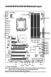
...® ICH10R JMB322 JMB322 PCI2 IT8720 TPM_IC* M_BIOS B_BIOS TSB43AB23 PCIEX8_1 GIGABYTE SATA2 PWR_LED CI Debug LED(Note 2) IDE NB PHASE LED SATA2_1 SATA2_0 SATA2_3 SATA2_2 SATA2_5 SATA2_4 GSATA2_1 GSATA2_0 GSATA2_3 GSATA2_2 FDD F1_1394 F_USB2 F_PANEL "*" Only for GA-EX58-UD5P. GA-EX58-UD5P/GA-EX58-UD5 Motherboard Layout KB_MS SYS_FAN3 R_SPDIF V1394-1 ATX_12V_2X CMOS_SW R_USB CPU Voltage...
...® ICH10R JMB322 JMB322 PCI2 IT8720 TPM_IC* M_BIOS B_BIOS TSB43AB23 PCIEX8_1 GIGABYTE SATA2 PWR_LED CI Debug LED(Note 2) IDE NB PHASE LED SATA2_1 SATA2_0 SATA2_3 SATA2_2 SATA2_5 SATA2_4 GSATA2_1 GSATA2_0 GSATA2_3 GSATA2_2 FDD F1_1394 F_USB2 F_PANEL "*" Only for GA-EX58-UD5P. GA-EX58-UD5P/GA-EX58-UD5 Motherboard Layout KB_MS SYS_FAN3 R_SPDIF V1394-1 ATX_12V_2X CMOS_SW R_USB CPU Voltage...

Manual
Page 10
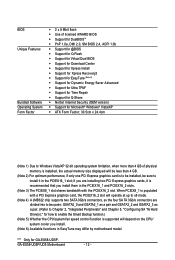
...IEEE 1394a headers) GA-EX58-UD5P/UD5 Motherboard - 10 - Support for SATA RAID 0, RAID 1 and JBOD iTE IT8720 chip: - 1 x floppy disk drive connector supporting up to 1 floppy disk drive T.I. Support for SATA RAID 0, RAID 1, RAID 5, and RAID 10 GIGABYTE SATA2 chip: -...system memory (Note 1) Dual/3 channel memory architecture Support for DDR3 2100/1333/1066/800 MHz memory modules (Go to GIGABYTE's website for the latest memory support list.) Realtek ALC889A codec High Definition Audio 2/4/5.1/7.1-channel Support ...
...IEEE 1394a headers) GA-EX58-UD5P/UD5 Motherboard - 10 - Support for SATA RAID 0, RAID 1 and JBOD iTE IT8720 chip: - 1 x floppy disk drive connector supporting up to 1 floppy disk drive T.I. Support for SATA RAID 0, RAID 1, RAID 5, and RAID 10 GIGABYTE SATA2 chip: -...system memory (Note 1) Dual/3 channel memory architecture Support for DDR3 2100/1333/1066/800 MHz memory modules (Go to GIGABYTE's website for the latest memory support list.) Realtek ALC889A codec High Definition Audio 2/4/5.1/7.1-channel Support ...
Manual
Page 12
... sure to install it is recommended that you install. (Note 6) Available functions in EasyTune may differ by motherboard model. GA-EX58-UD5P/UD5 Motherboard - 12 - When PCIEX8_1 is populated with the PCIEX16_2 slot. "*" Only for GA-EX58-UD5P. BIOS Unique Features Bundled Software Operating System Form Factor 2 x 8 Mbit flash Use of physical memory...
... sure to install it is recommended that you install. (Note 6) Available functions in EasyTune may differ by motherboard model. GA-EX58-UD5P/UD5 Motherboard - 12 - When PCIEX8_1 is populated with the PCIEX16_2 slot. "*" Only for GA-EX58-UD5P. BIOS Unique Features Bundled Software Operating System Form Factor 2 x 8 Mbit flash Use of physical memory...
Manual
Page 14
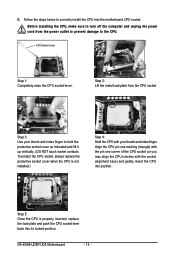
... CPU socket lever. Step 2: Lift the metal load plate from the power outlet to prevent damage to correctly install the CPU into its locked position. GA-EX58-UD5P/UD5 Motherboard - 14 - Follow the steps below to the CPU. Align the CPU pin one marking (triangle) with the pin one corner of the CPU...
... CPU socket lever. Step 2: Lift the metal load plate from the power outlet to prevent damage to correctly install the CPU into its locked position. GA-EX58-UD5P/UD5 Motherboard - 14 - Follow the steps below to the CPU. Align the CPU pin one marking (triangle) with the pin one corner of the CPU...

Manual
Page 16
... memory. Intel ® Flex Memory Technology offers greater flexibility to upgrade by allowing dif ferent memory sizes to be used. (Go to GIGABYTE's website for the latest memory support list.) • Always turn off the computer and unplug the power cord from the power outlet before... Dual Channel mode with three, four or six modules, it is recommended that memory of the same capacity, brand, speed, and chips be used . GA-EX58-UD5P/UD5 Motherboard - 16 - DS/SS - - Dual Channel-1. A memory module can be used . When enabling 3 Channel mode with two or four modules,...
... memory. Intel ® Flex Memory Technology offers greater flexibility to upgrade by allowing dif ferent memory sizes to be used. (Go to GIGABYTE's website for the latest memory support list.) • Always turn off the computer and unplug the power cord from the power outlet before... Dual Channel mode with three, four or six modules, it is recommended that memory of the same capacity, brand, speed, and chips be used . GA-EX58-UD5P/UD5 Motherboard - 16 - DS/SS - - Dual Channel-1. A memory module can be used . When enabling 3 Channel mode with two or four modules,...
Manual
Page 18
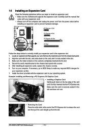
... the card and then pull the card straight up from the chassis back panel. 2. Make sure the card is securely seated in the expansion slot. 1. GA-EX58-UD5P/UD5 Motherboard - 18 - Make sure the metal contacts on the card until it is fully inserted into the slot. 4. Install the driver provided with a screw...
... the card and then pull the card straight up from the chassis back panel. 2. Make sure the card is securely seated in the expansion slot. 1. GA-EX58-UD5P/UD5 Motherboard - 18 - Make sure the metal contacts on the card until it is fully inserted into the slot. 4. Install the driver provided with a screw...
Manual
Page 20
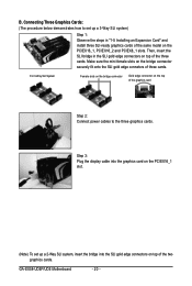
GA-EX58-UD5P/UD5 Motherboard - 20 - For 3-Way SLI System Female slots on the bridge connector Gold edge connector on top of the graphics card Step 2: Connect power cables ...
GA-EX58-UD5P/UD5 Motherboard - 20 - For 3-Way SLI System Female slots on the bridge connector Gold edge connector on top of the graphics card Step 2: Connect power cables ...

Manual
Page 22
... secure the SATA bracket to hardware. • Insert the SATA signal cable and SATA power cable securely into to the SATA port on your motherboard. GA-EX58-UD5P/UD5 Motherboard - 22 - nector on the bracket. the external SATA con- 1-7 Installing the SATA Bracket The SATA bracket allows you only need to your SATA...
... secure the SATA bracket to hardware. • Insert the SATA signal cable and SATA power cable securely into to the SATA port on your motherboard. GA-EX58-UD5P/UD5 Motherboard - 22 - nector on the bracket. the external SATA con- 1-7 Installing the SATA Bracket The SATA bracket allows you only need to your SATA...

Manual
Page 24
Line In Jack (Blue) The default line in Chapter 5, "Configuring 2/4/5.1/7.1-Channel Audio." GA-EX58-UD5P/UD5 Motherboard - 24 - This jack can be connected to this audio jack to connect center/subwoofer speakers in a 5.1/7.1-channel audio configuration. Microphones must be reconfigured to ...
Line In Jack (Blue) The default line in Chapter 5, "Configuring 2/4/5.1/7.1-Channel Audio." GA-EX58-UD5P/UD5 Motherboard - 24 - This jack can be connected to this audio jack to connect center/subwoofer speakers in a 5.1/7.1-channel audio configuration. Microphones must be reconfigured to ...

Manual
Page 26
Quick Switches This motherboard has 3 quick switches: power switch, reset switch and clearing CMOS switch, allowing users to quickly turn on/off or reset the system or clear the CMOS values. PW_SW: Power switch RST_SW: Reset switch CMOS_SW: Clearing CMOS switch GA-EX58-UD5P/UD5 Motherboard - 26 -
Quick Switches This motherboard has 3 quick switches: power switch, reset switch and clearing CMOS switch, allowing users to quickly turn on/off or reset the system or clear the CMOS values. PW_SW: Power switch RST_SW: Reset switch CMOS_SW: Clearing CMOS switch GA-EX58-UD5P/UD5 Motherboard - 26 -

Manual
Page 28
... Definition 3.3V -12V GND PS_ON(soft On/Off) GND GND GND -5V +5V +5V +5V (Only for 2x12 pinATX) GND (Only for 2x12 pinATX) GA-EX58-UD5P/UD5 Motherboard - 28 - The power connector possesses a foolproof design. The 12V power connector mainly supplies power to the power connector in the correct orientation. If the...
... Definition 3.3V -12V GND PS_ON(soft On/Off) GND GND GND -5V +5V +5V +5V (Only for 2x12 pinATX) GND (Only for 2x12 pinATX) GA-EX58-UD5P/UD5 Motherboard - 28 - The power connector possesses a foolproof design. The 12V power connector mainly supplies power to the power connector in the correct orientation. If the...

Manual
Page 30
... example, master or slave). (For information about configuring master/slave settings for the IDE devices, read the instructions from the device manufacturers.) 39 1 40 2 GA-EX58-UD5P/UD5 Motherboard - 30 - If you wish to connect two IDE devices, remember to set the jumpers and the cabling according to the role of the connector...
... example, master or slave). (For information about configuring master/slave settings for the IDE devices, read the instructions from the device manufacturers.) 39 1 40 2 GA-EX58-UD5P/UD5 Motherboard - 30 - If you wish to connect two IDE devices, remember to set the jumpers and the cabling according to the role of the connector...

Manual
Page 32
10) GSATA2_0/1/2/3 (SATA 3Gb/s Connectors, Controlled by GIGABYTE SATA2/JMB322) The SATA connectors conform to Chapter 2, "Integrated Peripherals" and Chapter 5, "Configuring SATA Hard Drive(s)," for instructions on when the system is operating. The ... TA 3Gb/s standard and are compatible with SA TA 1.5Gb/s standard. The GIGABYTE SATA2/JMB322 controller supports RAID 0, RAID 1 and JBOD. The LED is off when the system is in S3/S4 sleep state or powered off (S5). 1 GA-EX58-UD5P/UD5 Motherboard - 32 - System Status LED S0 On S1 Blinking S3/S4/S5...
10) GSATA2_0/1/2/3 (SATA 3Gb/s Connectors, Controlled by GIGABYTE SATA2/JMB322) The SATA connectors conform to Chapter 2, "Integrated Peripherals" and Chapter 5, "Configuring SATA Hard Drive(s)," for instructions on when the system is operating. The ... TA 3Gb/s standard and are compatible with SA TA 1.5Gb/s standard. The GIGABYTE SATA2/JMB322 controller supports RAID 0, RAID 1 and JBOD. The LED is off when the system is in S3/S4 sleep state or powered off (S5). 1 GA-EX58-UD5P/UD5 Motherboard - 32 - System Status LED S0 On S1 Blinking S3/S4/S5...

Manual
Page 34
..., please contact the chassis manufacturer. 14) CD_IN (CD In Connector) You may connect your optical drive to this header. Definition 1 1 CD-L 2 GND 3 GND 4 CD-R GA-EX58-UD5P/UD5 Motherboard - 34 - Incorrect connection between the module connector and the motherboard header will be present on each wire instead of a single plug. If you want...
..., please contact the chassis manufacturer. 14) CD_IN (CD In Connector) You may connect your optical drive to this header. Definition 1 1 CD-L 2 GND 3 GND 4 CD-R GA-EX58-UD5P/UD5 Motherboard - 34 - Incorrect connection between the module connector and the motherboard header will be present on each wire instead of a single plug. If you want...

Manual
Page 36
... prevent damage to IEEE 1394a specification. For purchasing the additional IEEE 1394a bracket(s), please contact the local dealer. Ensure that the cable is securely connected. GA-EX58-UD5P/UD5 Motherboard - 36 - Each IEEE 1394a header can provide two USB ports via an optional IEEE 1394a bracket. 17) F_USB1/F_USB2 (USB Headers) The headers...
... prevent damage to IEEE 1394a specification. For purchasing the additional IEEE 1394a bracket(s), please contact the local dealer. Ensure that the cable is securely connected. GA-EX58-UD5P/UD5 Motherboard - 36 - Each IEEE 1394a header can provide two USB ports via an optional IEEE 1394a bracket. 17) F_USB1/F_USB2 (USB Headers) The headers...
Manual
Page 38
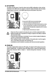
... to replace the battery by removing the battery: 1. Replace the battery when the battery voltage drops to Chapter 4, "Dynamic Energy Saver Advanced, " for one . GA-EX58-UD5P/UD5 Motherboard - 38 - Refer to a low level, or the CMOS values may not be accurate or may clear the CMOS values by yourself or uncertain about...
... to replace the battery by removing the battery: 1. Replace the battery when the battery voltage drops to Chapter 4, "Dynamic Energy Saver Advanced, " for one . GA-EX58-UD5P/UD5 Motherboard - 38 - Refer to a low level, or the CMOS values may not be accurate or may clear the CMOS values by yourself or uncertain about...
