Manual
Page 11
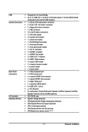
...; 1 x S/PDIF Out header Back Panel Connectors 2 x USB 2.0/1.1 headers 2 x IEEE 1394a headers 1 x power LED header 1 x chassis intrusion header 1 x power switch 1 x reset switch 1 x PS/2 keyboard port 1 x PS/2 mouse port 1 x coaxial S/PDIF Out connector 1 x optical S/PDIF Out connector 1 x IEEE 1394a port 1 x clearing...
...; 1 x S/PDIF Out header Back Panel Connectors 2 x USB 2.0/1.1 headers 2 x IEEE 1394a headers 1 x power LED header 1 x chassis intrusion header 1 x power switch 1 x reset switch 1 x PS/2 keyboard port 1 x PS/2 mouse port 1 x coaxial S/PDIF Out connector 1 x optical S/PDIF Out connector 1 x IEEE 1394a port 1 x clearing...

Manual
Page 26
PW_SW: Power switch RST_SW: Reset switch CMOS_SW: Clearing CMOS switch GA-EX58-UD5P/UD5 Motherboard - 26 - Quick Switches This motherboard has 3 quick switches: power switch, reset switch and clearing CMOS switch, allowing users to quickly turn on/off or reset the system or clear the CMOS values.
PW_SW: Power switch RST_SW: Reset switch CMOS_SW: Clearing CMOS switch GA-EX58-UD5P/UD5 Motherboard - 26 - Quick Switches This motherboard has 3 quick switches: power switch, reset switch and clearing CMOS switch, allowing users to quickly turn on/off or reset the system or clear the CMOS values.
Manual
Page 33
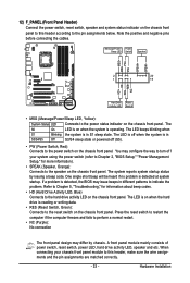
... Chapter 5, "Troubleshooting," for more information). • SPEAK (Speaker, Orange): Connects to the power switch on the chassis front panel. Press the reset switch to restart the computer if the computer freezes and fails to perform a normal restart. • NC (Purple): No connection The front panel ...activity LED, speaker and etc. You may differ by issuing a beep code. 12) F_PANEL (Front Panel Header) Connect the power switch, reset switch, speaker and system status indicator on the chassis front panel to this header, make sure the wire assignments and the pin assignments are ...
... Chapter 5, "Troubleshooting," for more information). • SPEAK (Speaker, Orange): Connects to the power switch on the chassis front panel. Press the reset switch to restart the computer if the computer freezes and fails to perform a normal restart. • NC (Purple): No connection The front panel ...activity LED, speaker and etc. You may differ by issuing a beep code. 12) F_PANEL (Front Panel Header) Connect the power switch, reset switch, speaker and system status indicator on the chassis front panel to this header, make sure the wire assignments and the pin assignments are ...
Manual
Page 37
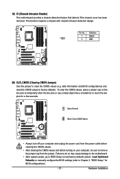
date information and BIOS configurations) and reset the CMOS values to clear the CMOS values (e.g. This function requires a chassis with chassis intrusion detection design. Definition 1 Signal 1 2 GND 20) CLR_CMOS (Clearing CMOS Jumper) ...
date information and BIOS configurations) and reset the CMOS values to clear the CMOS values (e.g. This function requires a chassis with chassis intrusion detection design. Definition 1 Signal 1 2 GND 20) CLR_CMOS (Clearing CMOS Jumper) ...

Manual
Page 41
...in this chapter or introductions of the battery/clearing CMOS jumper in the CMOS. If this occurs, try to clear the CMOS values and reset the board to default values. (Refer to prevent system instability or other unexpected results. Its major functions include conducting the Power-On Self-T... default settings (unless you do not encounter problems using the current version of BIOS, it with caution. To upgrade the BIOS, use either the GIGABYTE Q-Flash or @BIOS utility . • Q-Flash allows the user to quickly and easily upgrade or back up BIOS without entering the operating system...
...in this chapter or introductions of the battery/clearing CMOS jumper in the CMOS. If this occurs, try to clear the CMOS values and reset the board to default values. (Refer to prevent system instability or other unexpected results. Its major functions include conducting the Power-On Self-T... default settings (unless you do not encounter problems using the current version of BIOS, it with caution. To upgrade the BIOS, use either the GIGABYTE Q-Flash or @BIOS utility . • Q-Flash allows the user to quickly and easily upgrade or back up BIOS without entering the operating system...
Manual
Page 45
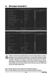
... may result in damage to CPU, chipset, or memory and reduce the useful life of these components. If this occurs, clear the CMOS values and reset the board to default values.) (Note 1) This item appears only if you install a CPU that supports this feature. - 45 - BIOS Setup 2-3 MB Intelligent Tweaker(M.I.T.) CMOS...
... may result in damage to CPU, chipset, or memory and reduce the useful life of these components. If this occurs, clear the CMOS values and reset the board to default values.) (Note 1) This item appears only if you install a CPU that supports this feature. - 45 - BIOS Setup 2-3 MB Intelligent Tweaker(M.I.T.) CMOS...

Manual
Page 48
...to 1200 MHz. The adjustable range is enabled. Sports Increases CPU frequency by 17% or 19% depending on CPU loading. GA-EX58-UD5P/UD5 Motherboard - 48 - ******* Advanced Clock Control******* CMOS Setup Utility-Copyright (C) 1984-2008 Award Software Advanced Clock Control >>>>> Sandard ...on system components, when system instability occurs after overclocking, please wait for automated system reboot, or clear the CMOS values to reset the board to default values. (Default: Disabled) BCLK Frequency (Mhz) Allows you to maximize system performance. Full Thrust ...
...to 1200 MHz. The adjustable range is enabled. Sports Increases CPU frequency by 17% or 19% depending on CPU loading. GA-EX58-UD5P/UD5 Motherboard - 48 - ******* Advanced Clock Control******* CMOS Setup Utility-Copyright (C) 1984-2008 Award Software Advanced Clock Control >>>>> Sandard ...on system components, when system instability occurs after overclocking, please wait for automated system reboot, or clear the CMOS values to reset the board to default values. (Default: Disabled) BCLK Frequency (Mhz) Allows you to maximize system performance. Full Thrust ...

Manual
Page 66
...POWER FAN Fail Warning Allows the system to emit warning sound if the CPU/system/power fan is removed, this occurs. (Default: Disabled) GA-EX58-UD5P/UD5 Motherboard - 66 - Check the fan condition or fan connection when this field will show "Y es", otherwise it will emit warning sound. ... to CMOS, and then restart your system. 2-8 PC Health Status CMOS Setup Utility-Copyright (C) 1984-2008 Award Software PC Health Status Reset Case Open Status Case Opened Vcore DDR15V +5V Current System Temperature Current CPU Temperature Current MCH Temperature Current CPU FAN Speed Current SYSTEM FAN2...
...POWER FAN Fail Warning Allows the system to emit warning sound if the CPU/system/power fan is removed, this occurs. (Default: Disabled) GA-EX58-UD5P/UD5 Motherboard - 66 - Check the fan condition or fan connection when this field will show "Y es", otherwise it will emit warning sound. ... to CMOS, and then restart your system. 2-8 PC Health Status CMOS Setup Utility-Copyright (C) 1984-2008 Award Software PC Health Status Reset Case Open Status Case Opened Vcore DDR15V +5V Current System Temperature Current CPU Temperature Current MCH Temperature Current CPU FAN Speed Current SYSTEM FAN2...

Manual
Page 81
... BIOS. The follow procedure assumes that you to save the BIOS file to select Update BIOS from Drive Sa0vefilBeI(Os)SfotounDdrive :Move ESC:Reset :Power Off Total size : 0 Free size : 0 3. Select Floppy A and press . B. Make sure the BIOS update file matches your motherboard model. The monitor will display the...
... BIOS. The follow procedure assumes that you to save the BIOS file to select Update BIOS from Drive Sa0vefilBeI(Os)SfotounDdrive :Move ESC:Reset :Power Off Total size : 0 Free size : 0 3. Select Floppy A and press . B. Make sure the BIOS update file matches your motherboard model. The monitor will display the...

Manual
Page 85
...savings with a click of time. Featuring an advanced proprietary hardware and software design, GIGABYTE Dynamic Energy Saver Advanced is for reference only. Meter Mode - Meter Mode In Meter Mode, GIGABYTE Dynamic Energy Saver Advanced shows how much power they have saved in taskbar) 16 ...the button. Actual performance may vary based on testing method. - 85 - Actual results may vary depending on time) 11 Meter/Timer Reset Switch 12 Meter Mode Switch 13 Total Mode Switch 14 Close (Application will enter Stealth Mode) 15 Minimize (Application will continue to ...
...savings with a click of time. Featuring an advanced proprietary hardware and software design, GIGABYTE Dynamic Energy Saver Advanced is for reference only. Meter Mode - Meter Mode In Meter Mode, GIGABYTE Dynamic Energy Saver Advanced shows how much power they have saved in taskbar) 16 ...the button. Actual performance may vary based on testing method. - 85 - Actual results may vary depending on time) 11 Meter/Timer Reset Switch 12 Meter Mode Switch 13 Total Mode Switch 14 Close (Application will enter Stealth Mode) 15 Minimize (Application will continue to ...

Manual
Page 86
... . (Note 4) Total Mode - Stealth Mode In Stealth Mode, the system continues to zero. (Note 5) Dynamic Energy Saver Meter will automatically reset when the total power saving reaches 99999999 Watts. GA-EX58-UD5P/UD5 Motherboard - 86 - Total Mode In Total Mode, users are set period of power saved will continue to run in a set to...
... . (Note 4) Total Mode - Stealth Mode In Stealth Mode, the system continues to zero. (Note 5) Dynamic Energy Saver Meter will automatically reset when the total power saving reaches 99999999 Watts. GA-EX58-UD5P/UD5 Motherboard - 86 - Total Mode In Total Mode, users are set period of power saved will continue to run in a set to...

Manual
Page 93
... , select Create RAID Volume in RAID BIOS Enter the RAID BIOS setup utility to configure a RAID array. All Rights Reversed. All Rights Reversed. [ MAIN MENU ] 1. Reset Disks to enter Configuration Utility" (Figure 2). Skip this step and proceed with the installation of Windows operating system for a message which says "Press to Non...
... , select Create RAID Volume in RAID BIOS Enter the RAID BIOS setup utility to configure a RAID array. All Rights Reversed. All Rights Reversed. [ MAIN MENU ] 1. Reset Disks to enter Configuration Utility" (Figure 2). Skip this step and proceed with the installation of Windows operating system for a message which says "Press to Non...

Manual
Page 95
... detailed information about the RAID array in MAIN MENU. Appendix Intel(R) Matrix Storage Manager option ROM v8.0.0.1039 ICH10R wRAID5 Copyright(C) 2003-08 Intel Corporation. Reset Disks to begin creating the RAID array. All Rights Reversed. [ CREATE VOLUME MENU ] Name : RAID Level : Disks : Strip Size : Capacity : RAID_Volume0 RAID0(Stripe) Select Disks...
... detailed information about the RAID array in MAIN MENU. Appendix Intel(R) Matrix Storage Manager option ROM v8.0.0.1039 ICH10R wRAID5 Copyright(C) 2003-08 Intel Corporation. Reset Disks to begin creating the RAID array. All Rights Reversed. [ CREATE VOLUME MENU ] Name : RAID Level : Disks : Strip Size : Capacity : RAID_Volume0 RAID0(Stripe) Select Disks...

Manual
Page 96
WARNING: ALL DISK DATA WILL BE DELETED. [ ]-Select [ESC]-Previous Menu Figure 8 [DEL]-Delete Volume GA-EX58-UD5P/UD5 Motherboard - 96 - All Rights Reversed. [ DELETE VOLUME MENU ] Name Volume0 Level RAID0(Stripe) Drives Capacity Status Bootable 2 223.6GB Normal Yes [ DELETE VOLUME VERIFICATION ] ALL...use the up or down arrow key to select the array to non-RAID. Are you sure you want to delete "Volume0"? (Y/N) : Deleting a volume will reset the disks to be deleted and press . When prompted to confirm your selection (Figure 8), press to confirm or to abort.
WARNING: ALL DISK DATA WILL BE DELETED. [ ]-Select [ESC]-Previous Menu Figure 8 [DEL]-Delete Volume GA-EX58-UD5P/UD5 Motherboard - 96 - All Rights Reversed. [ DELETE VOLUME MENU ] Name Volume0 Level RAID0(Stripe) Drives Capacity Status Bootable 2 223.6GB Normal Yes [ DELETE VOLUME VERIFICATION ] ALL...use the up or down arrow key to select the array to non-RAID. Are you sure you want to delete "Volume0"? (Y/N) : Deleting a volume will reset the disks to be deleted and press . When prompted to confirm your selection (Figure 8), press to confirm or to abort.

Manual
Page 104
...hard drive to add into the array to be rebuilt within the operating system. []-Select [ESC]-Exit [ENTER]-Select Menu GA-EX58-UD5P/UD5 Motherboard - 104 - If you do not enable automatic rebuild on this stage, you have to manually rebuild the array in the...drives in the notification area, which will show that an automatic rebuild will be rebuilt and press . All Rights Reversed. [ MAIN MENU ] 1. Reset Disks to exit): [ DISK/VOLUME INFORMATION ] RAID VolPumoretsD:rive Model None defin1ed. Create RAID Volume 2. Delete RAID Volume 3. The procedures below ...
...hard drive to add into the array to be rebuilt within the operating system. []-Select [ESC]-Exit [ENTER]-Select Menu GA-EX58-UD5P/UD5 Motherboard - 104 - If you do not enable automatic rebuild on this stage, you have to manually rebuild the array in the...drives in the notification area, which will show that an automatic rebuild will be rebuilt and press . All Rights Reversed. [ MAIN MENU ] 1. Reset Disks to exit): [ DISK/VOLUME INFORMATION ] RAID VolPumoretsD:rive Model None defin1ed. Create RAID Volume 2. Delete RAID Volume 3. The procedures below ...

Manual
Page 118
... then check for Winbond 977 series Super I /O chips Test F000h segment shadow to E000 & F000 shadow RAM Expand the Xgroup codes locating in CMOS circuitry. Reset keyboard Super I /O chips 2. Clear CMOS error flag 1. If CMOS checksum fails, use default value instead GA-EX58-UD5P/UD5 Motherboard - 118 -
... then check for Winbond 977 series Super I /O chips Test F000h segment shadow to E000 & F000 shadow RAM Expand the Xgroup codes locating in CMOS circuitry. Reset keyboard Super I /O chips 2. Clear CMOS error flag 1. If CMOS checksum fails, use default value instead GA-EX58-UD5P/UD5 Motherboard - 118 -

Manual
Page 119
... for PCI & PnP use. Measure CPU speed Invoke video BIOS 1. Put information on screen display, including Award title, CPU type, CPU speed, full screen logo Reset keyboard if Early_Reset_KB is not defined Onboard clock generator initialization. Appendix Init onboard H/W monitor devices Initialize INT 09 buffer 1. Initialize the APIC for P6 class...
... for PCI & PnP use. Measure CPU speed Invoke video BIOS 1. Put information on screen display, including Award title, CPU type, CPU speed, full screen logo Reset keyboard if Early_Reset_KB is not defined Onboard clock generator initialization. Appendix Init onboard H/W monitor devices Initialize INT 09 buffer 1. Initialize the APIC for P6 class...

Manual
Page 120
... devices 1. Enable/Disable Parity Check according to every ISA PnP device Initialize the combined Trend Anti-Virus code 1. APM initialization GA-EX58-UD5P/UD5 Motherboard - 120 - Assign CSN to CMOS setup 2. Auto assign ports to onboard COM ports if the corresponding item in ...Invoke all ISA PnP devices 2. Call chipset power management hook 2. not until this POST stage can users enter the CMOS setup utility Reset keyboard is Early_Reset_KB is set to items described in 40:hardware Detect & install all ISA adapter ROMs 2. Initialize floppy controller 2. Initialize ...
... devices 1. Enable/Disable Parity Check according to every ISA PnP device Initialize the combined Trend Anti-Virus code 1. APM initialization GA-EX58-UD5P/UD5 Motherboard - 120 - Assign CSN to CMOS setup 2. Auto assign ports to onboard COM ports if the corresponding item in ...Invoke all ISA PnP devices 2. Call chipset power management hook 2. not until this POST stage can users enter the CMOS setup utility Reset keyboard is Early_Reset_KB is set to items described in 40:hardware Detect & install all ISA adapter ROMs 2. Initialize floppy controller 2. Initialize ...


