Manual
Page 1
GA-EX58-UD5P/ GA-EX58-UD5 LGA1366 socket motherboard for Intel® CoreTM i7 processor family User's Manual Rev. 1005 12ME-EX58UD5-1005R
GA-EX58-UD5P/ GA-EX58-UD5 LGA1366 socket motherboard for Intel® CoreTM i7 processor family User's Manual Rev. 1005 12ME-EX58UD5-1005R

Manual
Page 2
Motherboard GA-EX58-UD5P/GA-EX58-UD5 Oct. 31, 2008 Motherboard GA-EX58-UD5P/ GA-EX58-UD5 Oct. 31, 2008
Motherboard GA-EX58-UD5P/GA-EX58-UD5 Oct. 31, 2008 Motherboard GA-EX58-UD5P/ GA-EX58-UD5 Oct. 31, 2008
Manual
Page 3
...order to assist in this : "REV: X.X." Check your motherboard looks like this manual is protected by GIGABYTE without GIGABYTE's prior written permission. Disclaimer Information in the use GIGABYTE's unique features, read the User's Manual. For instructions on how to their respective owners. For... product-related information, check on our website at: http://www.gigabyte.com.tw Identifying Your Motherboard Revision The revision number on our website. Copyright © 2009 GIGA-BYTE TECHNOLOGY CO., LTD. Changes...
...order to assist in this : "REV: X.X." Check your motherboard looks like this manual is protected by GIGABYTE without GIGABYTE's prior written permission. Disclaimer Information in the use GIGABYTE's unique features, read the User's Manual. For instructions on how to their respective owners. For... product-related information, check on our website at: http://www.gigabyte.com.tw Identifying Your Motherboard Revision The revision number on our website. Copyright © 2009 GIGA-BYTE TECHNOLOGY CO., LTD. Changes...

Manual
Page 4
Table of Contents Box Contents ...6 Optional Items...6 GA-EX58-UD5P/GA-EX58-UD5 Motherboard Layout 7 Block Diagram...8 Chapter 1 Hardware Installation 9 1-1 Installation Precautions 9 1-2 Product Specifications 10 1-3 Installing the CPU and CPU Cooler 13 1-3-1 Installing the CPU 13 1-3-2 Installing the ...
Table of Contents Box Contents ...6 Optional Items...6 GA-EX58-UD5P/GA-EX58-UD5 Motherboard Layout 7 Block Diagram...8 Chapter 1 Hardware Installation 9 1-1 Installation Precautions 9 1-2 Product Specifications 10 1-3 Installing the CPU and CPU Cooler 13 1-3-1 Installing the CPU 13 1-3-2 Installing the ...
Manual
Page 5
......87 4-6 Q-Share ...88 4-7 Time Repair ...89 4-8 Teaming ...90 Chapter 5 Appendix ...91 5-1 Configuring SATA Hard Drive(s 91 5-1-1 Configuring Intel ICH10R SATA Controllers 91 5-1-2 Configuring GIGABYTE SATA2/JMB322 SATA Controller 97 5-1-3 Making a SATA RAID/AHCI Driver Diskette 99 5-1-4 Installing the SATA RAID/AHCI Driver and Operating System 101 5-1-5 Smart Backup Utility... the Sound Recorder 114 5-3 Troubleshooting 115 5-3-1 Frequently Asked Questions 115 5-3-2 Troubleshooting Procedure 116 5-4 POST Error Code 118 5-5 Regulatory Statements 122 "*" Only for GA-EX58-UD5P. - 5 -
......87 4-6 Q-Share ...88 4-7 Time Repair ...89 4-8 Teaming ...90 Chapter 5 Appendix ...91 5-1 Configuring SATA Hard Drive(s 91 5-1-1 Configuring Intel ICH10R SATA Controllers 91 5-1-2 Configuring GIGABYTE SATA2/JMB322 SATA Controller 97 5-1-3 Making a SATA RAID/AHCI Driver Diskette 99 5-1-4 Installing the SATA RAID/AHCI Driver and Operating System 101 5-1-5 Smart Backup Utility... the Sound Recorder 114 5-3 Troubleshooting 115 5-3-1 Frequently Asked Questions 115 5-3-2 Troubleshooting Procedure 116 5-4 POST Error Code 118 5-5 Regulatory Statements 122 "*" Only for GA-EX58-UD5P. - 5 -

Manual
Page 6
...-0*R) 2-port SATA power cable (Part No. 12CF1-2SERPW-0*R) S/PDIF in cable (Part No. 12CR1-1SPDIN-0*R) - 6 - The box contents are for reference only. Box Contents GA-EX58-UD5P/GA-EX58-UD5 motherboard Motherboard driver disk User's Manual Quick Installation Guide One IDE cable Four SATA 3Gb/s cables One SATA bracket I/O shield 2-Way SLI bridge connector 3-Way...
...-0*R) 2-port SATA power cable (Part No. 12CF1-2SERPW-0*R) S/PDIF in cable (Part No. 12CR1-1SPDIN-0*R) - 6 - The box contents are for reference only. Box Contents GA-EX58-UD5P/GA-EX58-UD5 motherboard Motherboard driver disk User's Manual Quick Installation Guide One IDE cable Four SATA 3Gb/s cables One SATA bracket I/O shield 2-Way SLI bridge connector 3-Way...
Manual
Page 7
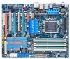
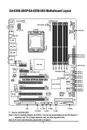
...information, please refer to a hardware limitation, the PCIEX1_1 slot can only accommodate a shorter PCI Express x1 expansion card. GA-EX58-UD5P/GA-EX58-UD5 Motherboard Layout KB_MS SYS_FAN3 R_SPDIF V1394-1 ATX_12V_2X CMOS_SW R_USB CPU Voltage L1/2/3 LGA1366 CPU_FAN CPU TEMP L1/2 PW_SW FREQ. ...NB Voltage L1/2/3 PCIEX16_1 PCI1 GA-EX58-UD5P/GA-EX58-UD5 PCIEX16_2 DDR3_2 DDR3_1 DDR3_4 DDR3_3 DDR3_6 DDR3_5 SYS_FAN1 SB Voltage L1/2/3 BATTERY CLR_CMOS Intel® ICH10R JMB322 JMB322 PCI2 IT8720 TPM_IC* M_BIOS B_BIOS TSB43AB23 PCIEX8_1 GIGABYTE SATA2 PWR_LED CI Debug LED(Note...
...information, please refer to a hardware limitation, the PCIEX1_1 slot can only accommodate a shorter PCI Express x1 expansion card. GA-EX58-UD5P/GA-EX58-UD5 Motherboard Layout KB_MS SYS_FAN3 R_SPDIF V1394-1 ATX_12V_2X CMOS_SW R_USB CPU Voltage L1/2/3 LGA1366 CPU_FAN CPU TEMP L1/2 PW_SW FREQ. ...NB Voltage L1/2/3 PCIEX16_1 PCI1 GA-EX58-UD5P/GA-EX58-UD5 PCIEX16_2 DDR3_2 DDR3_1 DDR3_4 DDR3_3 DDR3_6 DDR3_5 SYS_FAN1 SB Voltage L1/2/3 BATTERY CLR_CMOS Intel® ICH10R JMB322 JMB322 PCI2 IT8720 TPM_IC* M_BIOS B_BIOS TSB43AB23 PCIEX8_1 GIGABYTE SATA2 PWR_LED CI Debug LED(Note...
Manual
Page 8
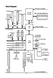
... PCIe CLK (100 MHz) x1 LAN2 LAN1 RJ45 RJ45 RTL RTL 8111D 8111D x1 x1 PCI Express Bus 2 SATA 3Gb/s 2 SATA 3Gb/s JMB322 JMB322 x1 GIGABYTE SATA2 ATA-133/100/66/33 IDE Channel PCI Bus TSB43AB23 QPI Interface Intel® X58 IOH CLK (133 MHz) Intel® ICH10R Dual BIOS... Speaker Out Center/Subwoofer Speaker Out Side Speaker Out MIC Line-Out Line-In SPDIF In SPDIF Out 2 PCI PCI CLK (33 MHz) "*" Only for GA-EX58-UD5P. - 8 -
... PCIe CLK (100 MHz) x1 LAN2 LAN1 RJ45 RJ45 RTL RTL 8111D 8111D x1 x1 PCI Express Bus 2 SATA 3Gb/s 2 SATA 3Gb/s JMB322 JMB322 x1 GIGABYTE SATA2 ATA-133/100/66/33 IDE Channel PCI Bus TSB43AB23 QPI Interface Intel® X58 IOH CLK (133 MHz) Intel® ICH10R Dual BIOS... Speaker Out Center/Subwoofer Speaker Out Side Speaker Out MIC Line-Out Line-In SPDIF In SPDIF Out 2 PCI PCI CLK (33 MHz) "*" Only for GA-EX58-UD5P. - 8 -
Manual
Page 9
Prior to installation, carefully read the user's manual and follow these procedures: • Prior to installation, do not allow screws to come in contact with the motherboard circuit or its components. • Make sure there are no leftover screws or metal components placed on the motherboard or within an electrostatic shielding container. • Before unplugging the power supply cable from the motherboard, make sure the power supply has been turned off. • Before turning on the motherboard, make sure they are connected tightly and securely. • When handling the motherboard, ...
Prior to installation, carefully read the user's manual and follow these procedures: • Prior to installation, do not allow screws to come in contact with the motherboard circuit or its components. • Make sure there are no leftover screws or metal components placed on the motherboard or within an electrostatic shielding container. • Before unplugging the power supply cable from the motherboard, make sure the power supply has been turned off. • Before turning on the motherboard, make sure they are connected tightly and securely. • When handling the motherboard, ...

Manual
Page 10
... 10 GIGABYTE SATA2 chip: - 1 x IDE connector supporting ATA-133/100/66/33 and up to 2 IDE devices 2 x JMB322 chips (Smart Backup): - 4 x SATA 3Gb/s connectors ( GSATA2_0, GSATA2_1, GSATA2_2, GSATA2_3) supporting up to the internal IEEE 1394a headers) GA-EX58-UD5P/UD5 Motherboard - 10 ...memory (Note 1) Dual/3 channel memory architecture Support for DDR3 2100/1333/1066/800 MHz memory modules (Go to GIGABYTE's website for the latest memory support list.) Realtek ALC889A codec High Definition Audio 2/4/5.1/7.1-channel Support...
... 10 GIGABYTE SATA2 chip: - 1 x IDE connector supporting ATA-133/100/66/33 and up to 2 IDE devices 2 x JMB322 chips (Smart Backup): - 4 x SATA 3Gb/s connectors ( GSATA2_0, GSATA2_1, GSATA2_2, GSATA2_3) supporting up to the internal IEEE 1394a headers) GA-EX58-UD5P/UD5 Motherboard - 10 ...memory (Note 1) Dual/3 channel memory architecture Support for DDR3 2100/1333/1066/800 MHz memory modules (Go to GIGABYTE's website for the latest memory support list.) Realtek ALC889A codec High Definition Audio 2/4/5.1/7.1-channel Support...
Manual
Page 11
Hardware Installation USB Integrated in the South Bridge Up to 12 USB 2.0/1.1 ports (8 on the back panel, 4 via the USB brackets connected to the internal USB headers) Internal Connectors 1 x 24-pin ATX main power connector 1 x 8-pin ATX 12V power connector 1 x floppy disk drive connector 1 x IDE connector 10 x SATA 3Gb/s connectors 1 x CPU fan header 3 x system fan headers 1 x power fan header 1 x North Bridge fan header 1 x front panel header 1 x front panel audio ...
Hardware Installation USB Integrated in the South Bridge Up to 12 USB 2.0/1.1 ports (8 on the back panel, 4 via the USB brackets connected to the internal USB headers) Internal Connectors 1 x 24-pin ATX main power connector 1 x 8-pin ATX 12V power connector 1 x floppy disk drive connector 1 x IDE connector 10 x SATA 3Gb/s connectors 1 x CPU fan header 3 x system fan headers 1 x power fan header 1 x North Bridge fan header 1 x front panel header 1 x front panel audio ...
Manual
Page 12
"*" Only for GA-EX58-UD5P. GA-EX58-UD5P/UD5 Motherboard - 12 - if you install. (Note 6) Available functions in the PCIEX16_1 slot; When PCIEX8_1 is recommended that you install them in the PCIEX16_1 and PCIEX16_2 ...
"*" Only for GA-EX58-UD5P. GA-EX58-UD5P/UD5 Motherboard - 12 - if you install. (Note 6) Available functions in the PCIEX16_1 slot; When PCIEX8_1 is recommended that you install them in the PCIEX16_1 and PCIEX16_2 ...
Manual
Page 13
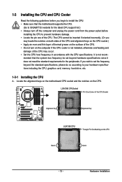
... - If you may occur. • Set the CPU host frequency in accordance with the CPU specifications. mended that the motherboard supports the CPU. (Go to GIGABYTE's website for the peripherals. Hardware Installation LGA1366 CPUSocket Pin One Corner of the CPU Socket Alignment Key Alignment Key LGA1366 CPU Triangle Pin One Marking...
... - If you may occur. • Set the CPU host frequency in accordance with the CPU specifications. mended that the motherboard supports the CPU. (Go to GIGABYTE's website for the peripherals. Hardware Installation LGA1366 CPUSocket Pin One Corner of the CPU Socket Alignment Key Alignment Key LGA1366 CPU Triangle Pin One Marking...
Manual
Page 14
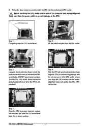
... the protective socket cover when the CPU is properly inserted, replace the load plate and push the CPU socket lever back into its locked position. B. GA-EX58-UD5P/UD5 Motherboard - 14 - Follow the steps below to hold the protective socket cover as indicated and lift it up vertically. (DO NOT touch socket contacts...
... the protective socket cover when the CPU is properly inserted, replace the load plate and push the CPU socket lever back into its locked position. B. GA-EX58-UD5P/UD5 Motherboard - 14 - Follow the steps below to hold the protective socket cover as indicated and lift it up vertically. (DO NOT touch socket contacts...
Manual
Page 15
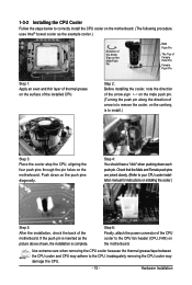
Check that the Male and Female push pins are joined closely. (Refer to your CPU cooler installation manual for instructions on installing the cooler.) Step 5: After the installation, check the back of the CPU cooler to the CPU fan header (CPU_FAN) on the motherboard. Use extreme care when removing the CPU cooler because the thermal grease/tape between the CPU cooler and CPU may damage the CPU. - 15 - Step 6: Finally, attach the power connector of the motherboard. Step 4: You should hear a "click" when pushing down on the push pins diagonally. Hardware Installation Step 2: ...
Check that the Male and Female push pins are joined closely. (Refer to your CPU cooler installation manual for instructions on installing the cooler.) Step 5: After the installation, check the back of the CPU cooler to the CPU fan header (CPU_FAN) on the motherboard. Use extreme care when removing the CPU cooler because the thermal grease/tape between the CPU cooler and CPU may damage the CPU. - 15 - Step 6: Finally, attach the power connector of the motherboard. Step 4: You should hear a "click" when pushing down on the push pins diagonally. Hardware Installation Step 2: ...

Manual
Page 16
... - Intel ® Flex Memory Technology offers greater flexibility to upgrade by allowing dif ferent memory sizes to be installed in Dual/3 Channel mode/performance. GA-EX58-UD5P/UD5 Motherboard - 16 - A memory module can be populated and remain in only one direction. DS/SS - - When enabling Dual Channel mode with two...in the DDR3_1 or DDR3_3. • When memory modules of the same capacity, brand, speed, and chips be used . (Go to GIGABYTE's website for the latest memory support list.) • Always turn off the computer and unplug the power cord from the power outlet before ...
... - Intel ® Flex Memory Technology offers greater flexibility to upgrade by allowing dif ferent memory sizes to be installed in Dual/3 Channel mode/performance. GA-EX58-UD5P/UD5 Motherboard - 16 - A memory module can be populated and remain in only one direction. DS/SS - - When enabling Dual Channel mode with two...in the DDR3_1 or DDR3_3. • When memory modules of the same capacity, brand, speed, and chips be used . (Go to GIGABYTE's website for the latest memory support list.) • Always turn off the computer and unplug the power cord from the power outlet before ...
Manual
Page 17
Step 1: Note the orientation of the socket will snap into the memory socket. Hardware Installation DDR3 and DDR2 DIMMs are not compatible to each other or DDR DIMMs. Be sure to install DDR3 DIMMs on the socket. Notch DDR3 DIMM A DDR3 memory module has a notch, so it vertically into place when the memory module is securely inserted. - 17 - Place the memory module on this motherboard. As indicated in the picture on the left, place your memory modules in one direction. Step 2: The clips at both ends of the memory module. Follow the steps below to the memory module. ...
Step 1: Note the orientation of the socket will snap into the memory socket. Hardware Installation DDR3 and DDR2 DIMMs are not compatible to each other or DDR DIMMs. Be sure to install DDR3 DIMMs on the socket. Notch DDR3 DIMM A DDR3 memory module has a notch, so it vertically into place when the memory module is securely inserted. - 17 - Place the memory module on this motherboard. As indicated in the picture on the left, place your memory modules in one direction. Step 2: The clips at both ends of the memory module. Follow the steps below to the memory module. ...
Manual
Page 18
... from the chassis back panel. 2. Example: Installing and Removing a PCI Express x16 Graphics Card: • Installing a Graphics Card: Gently push down on your card. GA-EX58-UD5P/UD5 Motherboard - 18 - Carefully read the manual that supports your computer. Install the driver provided with your expansion card(s). 7. Secure the card's metal bracket to the...
... from the chassis back panel. 2. Example: Installing and Removing a PCI Express x16 Graphics Card: • Installing a Graphics Card: Gently push down on your card. GA-EX58-UD5P/UD5 Motherboard - 18 - Carefully read the manual that supports your computer. Install the driver provided with your expansion card(s). 7. Secure the card's metal bracket to the...

Manual
Page 19
Before You Begin 1. We recommend a power supply that the exact power requirements will depend on your system. Hardware Installation Note that provides at least 1000W. Supported Operation Systems: Windows XP and Windows Vista operating systems are currently supported by the 2-Way SLI and 2-Way CrossFireX technologies. Power Requirements: Before installation, assure that support 3-Way CrossFireX technology include the Radeon HD 3800 series and Radeon HD 4800 series. Current ATI GPUs that the power supply you want to set up a single graphics card system, we recommend ...
Before You Begin 1. We recommend a power supply that the exact power requirements will depend on your system. Hardware Installation Note that provides at least 1000W. Supported Operation Systems: Windows XP and Windows Vista operating systems are currently supported by the 2-Way SLI and 2-Way CrossFireX technologies. Power Requirements: Before installation, assure that support 3-Way CrossFireX technology include the Radeon HD 3800 series and Radeon HD 4800 series. Current ATI GPUs that the power supply you want to set up a single graphics card system, we recommend ...
Manual
Page 20
GA-EX58-UD5P/UD5 Motherboard - 20 - Connecting Three Graphics Cards: (The procedure below demonstrates how to the three graphics cards. Step 3: Plug the display cable into the graphics card ...
GA-EX58-UD5P/UD5 Motherboard - 20 - Connecting Three Graphics Cards: (The procedure below demonstrates how to the three graphics cards. Step 3: Plug the display cable into the graphics card ...
