Manual
Page 1
GA-EP45T-DS3R/ GA-EP45T-DS3 LGA775 socket motherboard for Intel® CoreTM processor family/ Intel® Pentium® processor family/Intel® Celeron® processor family User's Manual Rev. 1001 12ME-EP45TDS3R-1001R
GA-EP45T-DS3R/ GA-EP45T-DS3 LGA775 socket motherboard for Intel® CoreTM processor family/ Intel® Pentium® processor family/Intel® Celeron® processor family User's Manual Rev. 1001 12ME-EP45TDS3R-1001R
Manual
Page 2
Motherboard GA-EP45T-DS3R/GA-EP45T-DS3R Jun. 20, 2008 Motherboard GA-EP45T-DS3R/ GA-EP45T-DS3 Jun. 20, 2008
Motherboard GA-EP45T-DS3R/GA-EP45T-DS3R Jun. 20, 2008 Motherboard GA-EP45T-DS3R/ GA-EP45T-DS3 Jun. 20, 2008
Manual
Page 4
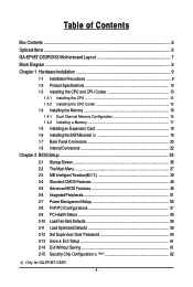
Table of Contents Box Contents ...6 OptionalItems ...6 GA-EP45T-DS3R/DS3 Motherboard Layout 7 Block Diagram ...8 Chapter 1 Hardware Installation 9 1-1 Installation Precautions 9 1-2 Product Specifications 10 1-3 Installing the CPU and CPU Cooler 13 1-3-1 Installing the CPU 13 1-3-2 Installing the ... 59 2-12 Set Supervisor/User Password 60 2-13 Save & Exit Setup 61 2-14 Exit Without Saving 61 2-15 Security Chip Configuration (Note 62 Only for GA-EP45T-DS3R. - 4 -
Table of Contents Box Contents ...6 OptionalItems ...6 GA-EP45T-DS3R/DS3 Motherboard Layout 7 Block Diagram ...8 Chapter 1 Hardware Installation 9 1-1 Installation Precautions 9 1-2 Product Specifications 10 1-3 Installing the CPU and CPU Cooler 13 1-3-1 Installing the CPU 13 1-3-2 Installing the ... 59 2-12 Set Supervisor/User Password 60 2-13 Save & Exit Setup 61 2-14 Exit Without Saving 61 2-15 Security Chip Configuration (Note 62 Only for GA-EP45T-DS3R. - 4 -
Manual
Page 6
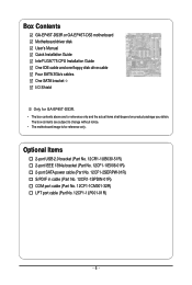
... COM port cable (Part No. 12CF1-1CM001-32R) LPT port cable (Part No. 12CF1-1LP001-01R) - 6 - Box Contents GA-EP45T-DS3R or GA-EP45T-DS3 motherboard Motherboard driver disk User's Manual Quick Installation Guide Intel® LGA775 CPU Installation Guide One IDE cable and one floppy disk drive cable... Four SATA 3Gb/s cables One SATA bracket I/O Shield Only for GA-EP45T-DS3R. • The box contents above are subject to ...
... COM port cable (Part No. 12CF1-1CM001-32R) LPT port cable (Part No. 12CF1-1LP001-01R) - 6 - Box Contents GA-EP45T-DS3R or GA-EP45T-DS3 motherboard Motherboard driver disk User's Manual Quick Installation Guide Intel® LGA775 CPU Installation Guide One IDE cable and one floppy disk drive cable... Four SATA 3Gb/s cables One SATA bracket I/O Shield Only for GA-EP45T-DS3R. • The box contents above are subject to ...
Manual
Page 7
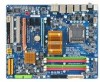
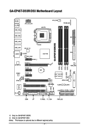
Only for GA-EP45T-DS3R. GA-EP45T-DS3R/DS3 Motherboard Layout KB_MS R_SPDIF ATX_12V_2X4 USB_1394_2 USB_1394_1 USB_LAN2 LGA775 CPU_FAN PHASE LED ATX GA-EP45T-DS3R/DS3 USB_LAN1 RTL8111C FDD AUDIO F_AUDIO Intel® P45 SYS_FAN1 PCIEX1_1 RTL8111C PCIEX16_1 PCIEX1_2 CODEC PCIEX1_3 SPDIF_I SPDIF_O PCIEX8_1 PCI1 DDR3_1 DDR3_2 DDR3_3 ... TPM IC (Note) F_USB2 F_USB1 IT8718 PCI2 CD_IN CI SATA2_4 SATA2_2 SATA2_0 SATA2_5 SATA2_3 SATA2_1 COMA LPT F_PANEL F1_1394 PWR_LED Only for GA-EP45T-DS3. (Note) This feature is optional due to different regional policy. - 7 -
Only for GA-EP45T-DS3R. GA-EP45T-DS3R/DS3 Motherboard Layout KB_MS R_SPDIF ATX_12V_2X4 USB_1394_2 USB_1394_1 USB_LAN2 LGA775 CPU_FAN PHASE LED ATX GA-EP45T-DS3R/DS3 USB_LAN1 RTL8111C FDD AUDIO F_AUDIO Intel® P45 SYS_FAN1 PCIEX1_1 RTL8111C PCIEX16_1 PCIEX1_2 CODEC PCIEX1_3 SPDIF_I SPDIF_O PCIEX8_1 PCI1 DDR3_1 DDR3_2 DDR3_3 ... TPM IC (Note) F_USB2 F_USB1 IT8718 PCI2 CD_IN CI SATA2_4 SATA2_2 SATA2_0 SATA2_5 SATA2_3 SATA2_1 COMA LPT F_PANEL F1_1394 PWR_LED Only for GA-EP45T-DS3. (Note) This feature is optional due to different regional policy. - 7 -
Manual
Page 8
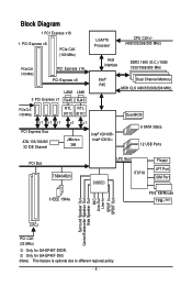
Only for GA-EP45T-DS3R. Block Diagram 1 PCI Express x16 1 PCI Express x8 PCIe CLK (100 MHz) PCIe CLK (100 MHz) PCI Express x16 PCI Express x8 LAN2 LAN1 3 PCI ... Speaker Out Center/Subwoofer Speaker Out Side Speaker Out MIC Line-Out Line-In SPDIF In SPDIF Out 2 PCI PCI CLK (33 MHz) Only for GA-EP45T-DS3. (Note) This feature is optional due to different regional policy. - 8 -
Only for GA-EP45T-DS3R. Block Diagram 1 PCI Express x16 1 PCI Express x8 PCIe CLK (100 MHz) PCIe CLK (100 MHz) PCI Express x16 PCI Express x8 LAN2 LAN1 3 PCI ... Speaker Out Center/Subwoofer Speaker Out Side Speaker Out MIC Line-Out Line-In SPDIF In SPDIF Out 2 PCI PCI CLK (33 MHz) Only for GA-EP45T-DS3. (Note) This feature is optional due to different regional policy. - 8 -
Manual
Page 10
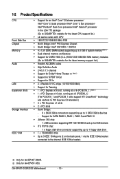
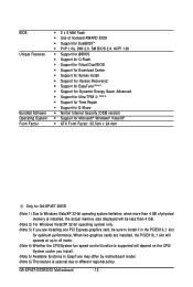
... and up to 2 IDE devices iTE IT8718 chip: - 1 x floppy disk drive connector supporting up to 6 SATA 3Gb/s devices - GA-EP45T-DS3R/DS3 Motherboard - 10 - TSB43AB23 chip Up to 3 IEEE 1394a ports (2 on the back panel, 1 via the IEEE 1394a bracket connected to...system memory (Note 1) Dual channel memory architecture Support for DDR3 1900 (O.C.)/1600/1333/1066/800 MHz memory modules (Go to GIGABYTE's website for the latest memory support list.) Realtek ALC889A codec High Definition Audio 2/4/5.1/7.1-channel Support for ...
... and up to 2 IDE devices iTE IT8718 chip: - 1 x floppy disk drive connector supporting up to 6 SATA 3Gb/s devices - GA-EP45T-DS3R/DS3 Motherboard - 10 - TSB43AB23 chip Up to 3 IEEE 1394a ports (2 on the back panel, 1 via the IEEE 1394a bracket connected to...system memory (Note 1) Dual channel memory architecture Support for DDR3 1900 (O.C.)/1600/1333/1066/800 MHz memory modules (Go to GIGABYTE's website for the latest memory support list.) Realtek ALC889A codec High Definition Audio 2/4/5.1/7.1-channel Support for ...
Manual
Page 12
... Security (OEM version) Š Support for Microsoft® Windows® Vista/XP Š ATX Form Factor; 30.5cm x 24.4cm Only for GA-EP45T-DS3R. (Note 1) Due to Windows Vista/XP 32-bit operating system limitation, when more than 4 GB of physical memory is installed, the actual memory size...2) For Windows Vista/XP 32-bit operating system only. (Note 3) If you install. (Note 5) Available functions in the PCIEX16_1 slot for optimum performance. GA-EP45T-DS3R/DS3 Motherboard - 12 - When two graphics cards are installed, the PCIEX16_1 slot will operate at up to different regional policy.
... Security (OEM version) Š Support for Microsoft® Windows® Vista/XP Š ATX Form Factor; 30.5cm x 24.4cm Only for GA-EP45T-DS3R. (Note 1) Due to Windows Vista/XP 32-bit operating system limitation, when more than 4 GB of physical memory is installed, the actual memory size...2) For Windows Vista/XP 32-bit operating system only. (Note 3) If you install. (Note 5) Available functions in the PCIEX16_1 slot for optimum performance. GA-EP45T-DS3R/DS3 Motherboard - 12 - When two graphics cards are installed, the PCIEX16_1 slot will operate at up to different regional policy.

Manual
Page 14
Step 2: Remove the protective socket cover. Step 3: Lift the metal load plate on the CPU socket. GA-EP45T-DS3R/DS3 Motherboard - 14 - Align the CPU pin one marking (triangle) with the pin one corner of the CPU socket (or you may align the CPU notches ...
Step 2: Remove the protective socket cover. Step 3: Lift the metal load plate on the CPU socket. GA-EP45T-DS3R/DS3 Motherboard - 14 - Align the CPU pin one marking (triangle) with the pin one corner of the CPU socket (or you may align the CPU notches ...

Manual
Page 16
...- - Intel® Flex Memory Technology offers greater flexibility to upgrade by allowing different memory sizes to be used . (Go to GIGABYTE's website for optimum performance. • Each channel can be installed in Flex Memory Mode will double the original memory bandwidth. After the...8226; Always turn off the computer and unplug the power cord from the power outlet before installing the memory in Dual Channel mode/performance. GA-EP45T-DS3R/DS3 Motherboard - 16 - If you begin to chipset limitation, read the following : Channel 0: DDR3_1, DDR3_2 Channel 1: DDR3_3, DDR3_4 Dual ...
...- - Intel® Flex Memory Technology offers greater flexibility to upgrade by allowing different memory sizes to be used . (Go to GIGABYTE's website for optimum performance. • Each channel can be installed in Flex Memory Mode will double the original memory bandwidth. After the...8226; Always turn off the computer and unplug the power cord from the power outlet before installing the memory in Dual Channel mode/performance. GA-EP45T-DS3R/DS3 Motherboard - 16 - If you begin to chipset limitation, read the following : Channel 0: DDR3_1, DDR3_2 Channel 1: DDR3_3, DDR3_4 Dual ...

Manual
Page 18
... from the power outlet before you begin to correctly install your expansion card(s). 7. Turn on the card until it is securely seated in the slot. 3. GA-EP45T-DS3R/DS3 Motherboard - 18 - • Removing the Card from the PCIEX8_1 slot: Press the white latch at the end of the card until it is fully inserted...
... from the power outlet before you begin to correctly install your expansion card(s). 7. Turn on the card until it is securely seated in the slot. 3. GA-EP45T-DS3R/DS3 Motherboard - 18 - • Removing the Card from the PCIEX8_1 slot: Press the white latch at the end of the card until it is fully inserted...

Manual
Page 20
... IEEE 1394 port supports the IEEE 1394a specification, featuring high speed, high bandwidth and hotplug capabilities. Before using this port for an IEEE 1394a device. GA-EP45T-DS3R/DS3 Motherboard - 20 - 1-7 Back Panel Connectors PS/2 Keyboard and PS/2 Mouse Port Use the upper port (green) to connect a PS/2 mouse and the lower port (purple...
... IEEE 1394 port supports the IEEE 1394a specification, featuring high speed, high bandwidth and hotplug capabilities. Before using this port for an IEEE 1394a device. GA-EP45T-DS3R/DS3 Motherboard - 20 - 1-7 Back Panel Connectors PS/2 Keyboard and PS/2 Mouse Port Use the upper port (green) to connect a PS/2 mouse and the lower port (purple...

Manual
Page 22
... sure your devices are compliant with the connectors you wish to connect. • Before installing the devices, be sure to the connector on the motherboard. GA-EP45T-DS3R/DS3 Motherboard - 22 - Unplug the power cord from the power outlet to prevent damage to the devices. • After installing the device and before connecting external...
... sure your devices are compliant with the connectors you wish to connect. • Before installing the devices, be sure to the connector on the motherboard. GA-EP45T-DS3R/DS3 Motherboard - 22 - Unplug the power cord from the power outlet to prevent damage to the devices. • After installing the device and before connecting external...

Manual
Page 24
... supplies a +12V power voltage and possesses a foolproof insertion design. For optimum heat dissipation, it in the correct orientation. The types of different color. 34 33 GA-EP45T-DS3R/DS3 Motherboard 2 1 - 24 - The pin 1 of a CPU fan with color-coded power connector wires. A red power connector wire indicates a positive connection and requires a +12V voltage. The...
... supplies a +12V power voltage and possesses a foolproof insertion design. For optimum heat dissipation, it in the correct orientation. The types of different color. 34 33 GA-EP45T-DS3R/DS3 Motherboard 2 1 - 24 - The pin 1 of a CPU fan with color-coded power connector wires. A red power connector wire indicates a positive connection and requires a +12V voltage. The...
Manual
Page 25
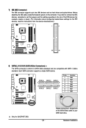
... SATA hard drive. Please connect the L-shaped end of the IDE devices (for example, master or slave). (For information about configuring master/slave settings for GA-EP45T-DS3. - 25 - Each SATA connector supports a single SATA device. SATA2_4 7 1 SATA2_5 SATA2_2 SATA2_3 SATA2_0 1 7 SATA2_1 Pin No. 1 2 3 4 5 6 7 Definition GND TXP TXN GND RXN RXP GND Only...
... SATA hard drive. Please connect the L-shaped end of the IDE devices (for example, master or slave). (For information about configuring master/slave settings for GA-EP45T-DS3. - 25 - Each SATA connector supports a single SATA device. SATA2_4 7 1 SATA2_5 SATA2_2 SATA2_3 SATA2_0 1 7 SATA2_1 Pin No. 1 2 3 4 5 6 7 Definition GND TXP TXN GND RXN RXP GND Only...

Manual
Page 26
...sleep state or powered off (S5). The LED is operating. 8) SATA2_0/1/2/3/4/5 (SATA 3Gb/s Connectors) The SATA connectors conform to Chapter 5, "Configuring SATA Hard Drive(s)," for GA-EP45T-DS3R. Definition 1 GND 2 TXP SATA2_4 SATA2_2 SATA2_0 3 TXN 7 4 GND 1 SATA2_5 SATA2_3 SATA2_1 5 RXN 6 RXP 7 GND Please connect the L-shaped end of the...System Status LED S0 On S1 Blinking S3/S4/S5 Off Only for instructions on when the system is on configuring a RAID array. GA-EP45T-DS3R/DS3 Motherboard - 26 - Each SATA connector supports a single SATA device.
...sleep state or powered off (S5). The LED is operating. 8) SATA2_0/1/2/3/4/5 (SATA 3Gb/s Connectors) The SATA connectors conform to Chapter 5, "Configuring SATA Hard Drive(s)," for GA-EP45T-DS3R. Definition 1 GND 2 TXP SATA2_4 SATA2_2 SATA2_0 3 TXN 7 4 GND 1 SATA2_5 SATA2_3 SATA2_1 5 RXN 6 RXP 7 GND Please connect the L-shaped end of the...System Status LED S0 On S1 Blinking S3/S4/S5 Off Only for instructions on when the system is on configuring a RAID array. GA-EP45T-DS3R/DS3 Motherboard - 26 - Each SATA connector supports a single SATA device.

Manual
Page 28
... AC'97 front panel audio module, refer to the instructions on each wire instead of the motherboard header. Pin No. Definition 1 CD-L 2 GND 3 GND 4 CD-R 1 GA-EP45T-DS3R/DS3 Motherboard - 28 - Make sure the wire assignments of the module connector match the pin assignments of a single plug. You may connect the audio cable that...
... AC'97 front panel audio module, refer to the instructions on each wire instead of the motherboard header. Pin No. Definition 1 CD-L 2 GND 3 GND 4 CD-R 1 GA-EP45T-DS3R/DS3 Motherboard - 28 - Make sure the wire assignments of the module connector match the pin assignments of a single plug. You may connect the audio cable that...

Manual
Page 30
... cord from the power outlet to prevent damage to the USB bracket. 16) F1_1394 (IEEE 1394a Header, Gray) The header conforms to IEEE 1394a specification. GA-EP45T-DS3R/DS3 Motherboard - 30 - For purchasing the optional USB bracket, please contact the local dealer. 10 9 2 1 Pin No. 1 2 3 4 5 6 7 8 9 10 Definition Power (5V) Power (5V) USB DXUSB DYUSB...
... cord from the power outlet to prevent damage to the USB bracket. 16) F1_1394 (IEEE 1394a Header, Gray) The header conforms to IEEE 1394a specification. GA-EP45T-DS3R/DS3 Motherboard - 30 - For purchasing the optional USB bracket, please contact the local dealer. 10 9 2 1 Pin No. 1 2 3 4 5 6 7 8 9 10 Definition Power (5V) Power (5V) USB DXUSB DYUSB...

Manual
Page 32
date information and BIOS configurations) and reset the CMOS values to remove the jumper cap from the jumper. GA-EP45T-DS3R/DS3 Motherboard - 32 - Open: Normal Short: Clear CMOS Values • Always turn off your computer and unplug the power cord from the power outlet before clearing ...
date information and BIOS configurations) and reset the CMOS values to remove the jumper cap from the jumper. GA-EP45T-DS3R/DS3 Motherboard - 32 - Open: Normal Short: Clear CMOS Values • Always turn off your computer and unplug the power cord from the power outlet before clearing ...

Manual
Page 34
GA-EP45T-DS3R/DS3 Motherboard - 34 -
GA-EP45T-DS3R/DS3 Motherboard - 34 -


