Manual
Page 9
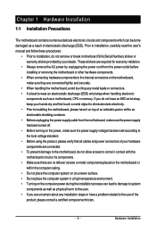
... Number) sticker or warranty sticker provided by your hands dry and first touch a metal object to eliminate static electricity. • Prior to installing the motherboard, please have a problem related to the use of the product, please consult a certified computer technician. - 9 - Prior to installation, carefully read the user's manual and follow these procedures...
... Number) sticker or warranty sticker provided by your hands dry and first touch a metal object to eliminate static electricity. • Prior to installing the motherboard, please have a problem related to the use of the product, please consult a certified computer technician. - 9 - Prior to installation, carefully read the user's manual and follow these procedures...

Manual
Page 26
...S4 sleep state or powered off your chassis front panel module to this header according to the power switch on the chassis front panel. GA-EP43-UD3L/US3L Motherboard - 26 - 11) F_PANEL (Front Panel Header) Connect the power switch, reset switch, speaker and system status indicator on the ... Switch, Red): Connects to the pin assignments below. Press the reset switch to restart the computer if the computer freezes and fails to indicate the problem. PW+ PWSPEAK+ SPEAK- 2 20 1 19 HD+ HD- Refer to Chapter 5, "Troubleshooting," for more information). • SPEAK (Speaker, Orange): ...
...S4 sleep state or powered off your chassis front panel module to this header according to the power switch on the chassis front panel. GA-EP43-UD3L/US3L Motherboard - 26 - 11) F_PANEL (Front Panel Header) Connect the power switch, reset switch, speaker and system status indicator on the ... Switch, Red): Connects to the pin assignments below. Press the reset switch to restart the computer if the computer freezes and fails to indicate the problem. PW+ PWSPEAK+ SPEAK- 2 20 1 19 HD+ HD- Refer to Chapter 5, "Troubleshooting," for more information). • SPEAK (Speaker, Orange): ...
Manual
Page 33
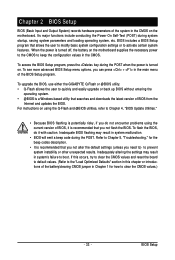
...power is a Windows-based utility that you need to) to prevent system instability or other unexpected results. To upgrade the BIOS, use either the GIGABYTE Q-Flash or @BIOS utility. • Q-Flash allows the user to clear the CMOS values.) - 33 - Refer to Chapter 5, "Troubleshooting,"...To see more advanced BIOS Setup menu options, you do not encounter problems using the Q-Flash and @BIOS utilities, refer to Chapter 4, "BIOS Update Utilities." • Because BIOS flashing is turned on the motherboard supplies the necessary power to the CMOS to activate certain system features. ...
...power is a Windows-based utility that you need to) to prevent system instability or other unexpected results. To upgrade the BIOS, use either the GIGABYTE Q-Flash or @BIOS utility. • Q-Flash allows the user to clear the CMOS values.) - 33 - Refer to Chapter 5, "Troubleshooting,"...To see more advanced BIOS Setup menu options, you do not encounter problems using the Q-Flash and @BIOS utilities, refer to Chapter 4, "BIOS Update Utilities." • Because BIOS flashing is turned on the motherboard supplies the necessary power to the CMOS to activate certain system features. ...

Manual
Page 51
... their Status fields will be the approximate distance to detect the status of the attached LAN cable. If no LAN cable is activated. When a Cable Problem Occurs... Part1-2 Status = Open Part3-6 Status = Open Part4-5 Status = Open Part7-8 Status = Open / Length = 0m / Length = 0m / Length = 0m ... F5: Previous Values +/-/PU/PD: Value F10: Save F6: Fail-Safe Defaults ESC: Exit F1: General Help F7: Optimized Defaults This motherboard incorporates cable diagnostic feature designed to the fault or short. Refer to a Gigabit hub or a 10/100 Mbps hub, the following information ...
... their Status fields will be the approximate distance to detect the status of the attached LAN cable. If no LAN cable is activated. When a Cable Problem Occurs... Part1-2 Status = Open Part3-6 Status = Open Part4-5 Status = Open Part7-8 Status = Open / Length = 0m / Length = 0m / Length = 0m ... F5: Previous Values +/-/PU/PD: Value F10: Save F6: Fail-Safe Defaults ESC: Exit F1: General Help F7: Optimized Defaults This motherboard incorporates cable diagnostic feature designed to the fault or short. Refer to a Gigabit hub or a 10/100 Mbps hub, the following information ...

Manual
Page 84
...to restart your motherboard has a clearing CMOS jumper, refer to the instructions on GIGABYTE's website. A: The following Award BIOS beep code descriptions may help you identify possible computer problems. (For ...reference only.) 1 short: System boots successfully 2 short: CMOS setting error 1 long, 1 short: Memory or motherboard error 1 long, 2 short: Monitor or graphics card error 1 long, 3 short: Keyboard error 1 long, 9 short: BIOS ROM error Continuous long beeps: Graphics card not inserted properly Continuous short beeps: Power error GA-EP43-UD3L/US3L Motherboard...
...to restart your motherboard has a clearing CMOS jumper, refer to the instructions on GIGABYTE's website. A: The following Award BIOS beep code descriptions may help you identify possible computer problems. (For ...reference only.) 1 short: System boots successfully 2 short: CMOS setting error 1 long, 1 short: Memory or motherboard error 1 long, 2 short: Monitor or graphics card error 1 long, 3 short: Keyboard error 1 long, 9 short: BIOS ROM error Continuous long beeps: Graphics card not inserted properly Continuous short beeps: Power error GA-EP43-UD3L/US3L Motherboard...
Manual
Page 85
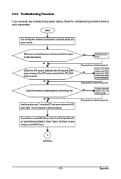
... Setup. Yes Check if the memory is verified and solved. The problem is verified and solved. Select "Save & Exit Setup" to the CPU securely. Press to the motherboard. Yes Insert the graphics card. The problem is verified and solved. Connect the CPU cooler power cable to enter... on the memory slot. A (Continued...) - 85 - Make sure the motherboard does not short-circuit with the chassis or other metal objects. Turn on the power to the CPU_FAN header properly? The problem is installed properly on the CPU. Is the power connector of the CPU cooler...
... Setup. Yes Check if the memory is verified and solved. The problem is verified and solved. Select "Save & Exit Setup" to the CPU securely. Press to the motherboard. Yes Insert the graphics card. The problem is verified and solved. Connect the CPU cooler power cable to enter... on the memory slot. A (Continued...) - 85 - Make sure the motherboard does not short-circuit with the chassis or other metal objects. Turn on the power to the CPU_FAN header properly? The problem is installed properly on the CPU. Is the power connector of the CPU cooler...
Manual
Page 86
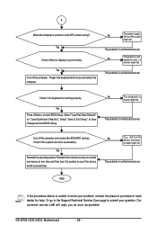
... Select "Save & Exit Setup" to enter BIOS Setup. No The keyboard or mouse might fail. Yes Reinstall the operating system. GA-EP43-UD3L/US3L Motherboard - 86 - The problem is verified and solved. Plugg in the keyboard and mouse and restart the computer. Yes Press to save changes and exit BIOS Setup...or "Load Optimized Defaults"). Reinstall other devices one by one (install one device at one time and then boot the system to solve your problem, contact the place of purchase or local dealer for help. A When the computer is turned on your question. No The IDE/SATA device...
... Select "Save & Exit Setup" to enter BIOS Setup. No The keyboard or mouse might fail. Yes Reinstall the operating system. GA-EP43-UD3L/US3L Motherboard - 86 - The problem is verified and solved. Plugg in the keyboard and mouse and restart the computer. Yes Press to save changes and exit BIOS Setup...or "Load Optimized Defaults"). Reinstall other devices one by one (install one device at one time and then boot the system to solve your problem, contact the place of purchase or local dealer for help. A When the computer is turned on your question. No The IDE/SATA device...


