Manual
Page 1
GA-EP41T-UD3L LGA775 socket motherboard for Intel® Core™ processor family/ Intel® Pentium® processor family/Intel® Celeron® processor family User's Manual Rev. 1101 12ME-41TUD3L-1101R
GA-EP41T-UD3L LGA775 socket motherboard for Intel® Core™ processor family/ Intel® Pentium® processor family/Intel® Celeron® processor family User's Manual Rev. 1101 12ME-41TUD3L-1101R
Manual
Page 2
Motherboard GA-EP41T-UD3L Nov. 12, 2009 Motherboard GA-EP41T-UD3L Nov. 12, 2009
Motherboard GA-EP41T-UD3L Nov. 12, 2009 Motherboard GA-EP41T-UD3L Nov. 12, 2009
Manual
Page 3
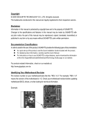
... copyright laws and is the property of the motherboard is 1.0. No part of the product, read the User's Manual. For product-related information, check on our website at: http://www.gigabyte.com.tw Identifying Your Motherboard Revision The revision number on how to their ...respective owners. Check your motherboard looks like this manual are legally registered to use of this product, GIGABYTE provides the following types of documentations: For ...
... copyright laws and is the property of the motherboard is 1.0. No part of the product, read the User's Manual. For product-related information, check on our website at: http://www.gigabyte.com.tw Identifying Your Motherboard Revision The revision number on how to their ...respective owners. Check your motherboard looks like this manual are legally registered to use of this product, GIGABYTE provides the following types of documentations: For ...
Manual
Page 4
Table of Contents Box Contents...6 Optional Items...6 GA-EP41T-UD3L Motherboard Layout 7 Block Diagram...8 Chapter 1 Hardware Installation 9 1-1 Installation Precautions 9 1-2 Product Specifications 10 1-3 Installing the CPU and CPU Cooler 13 1-3-1 Installing the CPU 13 1-3-2 Installing the CPU ...
Table of Contents Box Contents...6 Optional Items...6 GA-EP41T-UD3L Motherboard Layout 7 Block Diagram...8 Chapter 1 Hardware Installation 9 1-1 Installation Precautions 9 1-2 Product Specifications 10 1-3 Installing the CPU and CPU Cooler 13 1-3-1 Installing the CPU 13 1-3-2 Installing the CPU ...
Manual
Page 6
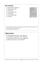
...-1FD001-7*R) 2-port USB 2.0 bracket (Part No. 12CR1-1UB030-5*R) 2-port SATA power cable (Part No. 12CF1-2SERPW-0*R) S/PDIF In cable (Part No. 12CR1-1SPDIN-0*R) - 6 - Box Contents GA-EP41T-UD3L motherboard Motherboard driver disk User's Manual Quick Installation Guide One IDE cable Two SATA 3Gb/s cables I/O Shield • The box contents above are subject to change without...
...-1FD001-7*R) 2-port USB 2.0 bracket (Part No. 12CR1-1UB030-5*R) 2-port SATA power cable (Part No. 12CF1-2SERPW-0*R) S/PDIF In cable (Part No. 12CR1-1SPDIN-0*R) - 6 - Box Contents GA-EP41T-UD3L motherboard Motherboard driver disk User's Manual Quick Installation Guide One IDE cable Two SATA 3Gb/s cables I/O Shield • The box contents above are subject to change without...
Manual
Page 7
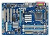
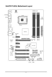
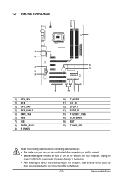
GA-EP41T-UD3L Motherboard Layout LPT KB_MS Coaxial Optical ATX_12V LGA775 PHASE_LED CPU_FAN PWR_FAN COM R_USB LAN USB F_AUDIO AUDIO SYS_FAN1 PCIEX1_1 RTL8111D PCIEX16 PCIEX1_2 CODEC PCIEX1_3 SPDIF_O CD_IN PCI1 SPDIF_I PCI2 IT8718 PCI3 FDD DDR3_1 DDR3_2 DDR3_3 DDR3_4 Intel® G41 ATX GA-EP41T-UD3L CLR_CMOS BAT Intel® ICH7 SATA2_0 SATA2_2 SYS_FAN2 SATA2_1 SATA2_3 IDE B_BIOS M_BIOS F_PANEL F_USB1 F_USB2 - 7 -
GA-EP41T-UD3L Motherboard Layout LPT KB_MS Coaxial Optical ATX_12V LGA775 PHASE_LED CPU_FAN PWR_FAN COM R_USB LAN USB F_AUDIO AUDIO SYS_FAN1 PCIEX1_1 RTL8111D PCIEX16 PCIEX1_2 CODEC PCIEX1_3 SPDIF_O CD_IN PCI1 SPDIF_I PCI2 IT8718 PCI3 FDD DDR3_1 DDR3_2 DDR3_3 DDR3_4 Intel® G41 ATX GA-EP41T-UD3L CLR_CMOS BAT Intel® ICH7 SATA2_0 SATA2_2 SYS_FAN2 SATA2_1 SATA2_3 IDE B_BIOS M_BIOS F_PANEL F_USB1 F_USB2 - 7 -

Manual
Page 9
...If you do not have an ESD wrist strap, keep your dealer. ponents such as a motherboard, CPU or memory. Hardware Installation Chapter 1 Hardware Installation 1-1 Installation Precautions The motherboard contains numerous delicate electronic circuits and components which can lead to damage to system components as ...been turned off. • Before turning on the power, make sure they are connected tightly and securely. • When handling the motherboard, avoid touching any metal leads or connectors. • It is best to wear an electrostatic discharge (ESD) wrist strap when handling ...
...If you do not have an ESD wrist strap, keep your dealer. ponents such as a motherboard, CPU or memory. Hardware Installation Chapter 1 Hardware Installation 1-1 Installation Precautions The motherboard contains numerous delicate electronic circuits and components which can lead to damage to system components as ...been turned off. • Before turning on the power, make sure they are connected tightly and securely. • When handling the motherboard, avoid touching any metal leads or connectors. • It is best to wear an electrostatic discharge (ESD) wrist strap when handling ...

Manual
Page 12
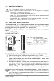
... on the DDR3_1 or DDR3_3 socket; to install two memory modules, we suggest that you install them on the DDR3_1 and DDR3_3 sockets. (Go to GIGABYTE's website for system usage, the actual memory size displayed will be less than 4 GB. (Note 2) Because of chipset limitations, to avoid the system being unable...
... on the DDR3_1 or DDR3_3 socket; to install two memory modules, we suggest that you install them on the DDR3_1 and DDR3_3 sockets. (Go to GIGABYTE's website for system usage, the actual memory size displayed will be less than 4 GB. (Note 2) Because of chipset limitations, to avoid the system being unable...
Manual
Page 13
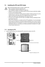
... alignment keys on the CPU socket.) • Apply an even and thin layer of thermal grease on the CPU. Locate the alignment keys on the motherboard CPU socket and the notches on the surface of the CPU may occur. • Set the CPU host frequency in accordance with the CPU specifications... meet the standard requirements for the latest CPU support list.) • Always turn on the computer if the CPU cooler is not recommended that the motherboard supports the CPU. (Go to GIGABYTE's website for the peripherals.
... alignment keys on the CPU socket.) • Apply an even and thin layer of thermal grease on the CPU. Locate the alignment keys on the motherboard CPU socket and the notches on the surface of the CPU may occur. • Set the CPU host frequency in accordance with the CPU specifications... meet the standard requirements for the latest CPU support list.) • Always turn on the computer if the CPU cooler is not recommended that the motherboard supports the CPU. (Go to GIGABYTE's website for the peripherals.
Manual
Page 14
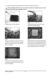
... socket cover from the power outlet to prevent damage to the CPU. Before installing the CPU, make sure to correctly install the CPU into the motherboard CPU socket. Align the CPU pin one marking (triangle) with the pin one corner of the CPU socket (or you may align the CPU notches...
... socket cover from the power outlet to prevent damage to the CPU. Before installing the CPU, make sure to correctly install the CPU into the motherboard CPU socket. Align the CPU pin one marking (triangle) with the pin one corner of the CPU socket (or you may align the CPU notches...

Manual
Page 15
... Before installing the cooler, note the direction of the arrow sign on the male push pin. (Turning the push pin along the direction of the motherboard. Step 4: You should hear a "click" when pushing down on installing the cooler.) Step 5: After the installation, check the back of arrow ... the cooler, on the contrary, is complete. 1-3-2 Installing the CPU Cooler Follow the steps below to correctly install the CPU cooler on the motherboard. (The following procedure uses Intel® boxed cooler as the picture above shows, the installation is to install.) Step 3: Place the cooler ...
... Before installing the cooler, note the direction of the arrow sign on the male push pin. (Turning the push pin along the direction of the motherboard. Step 4: You should hear a "click" when pushing down on installing the cooler.) Step 5: After the installation, check the back of arrow ... the cooler, on the contrary, is complete. 1-3-2 Installing the CPU Cooler Follow the steps below to correctly install the CPU cooler on the motherboard. (The following procedure uses Intel® boxed cooler as the picture above shows, the installation is to install.) Step 3: Place the cooler ...
Manual
Page 16
... - to install two memory modules, we suggest that memory of the same capacity, brand, speed, and chips be used . (Go to GIGABYTE's website for optimum performance. 3. A memory module can be used and installed in Dual Channel mode/performance. When enabling Dual Channel mode with ...Memory Read the following guidelines before you are unable to insert the memory, switch the direction. 1-4-1 Dual Channel Memory Configuration This motherboard provides four DDR3 memory sockets and supports Dual Channel Technology. DS/SS - - Intel Flex Memory Technology offers greater flexibility to ...
... - to install two memory modules, we suggest that memory of the same capacity, brand, speed, and chips be used . (Go to GIGABYTE's website for optimum performance. 3. A memory module can be used and installed in Dual Channel mode/performance. When enabling Dual Channel mode with ...Memory Read the following guidelines before you are unable to insert the memory, switch the direction. 1-4-1 Dual Channel Memory Configuration This motherboard provides four DDR3 memory sockets and supports Dual Channel Technology. DS/SS - - Intel Flex Memory Technology offers greater flexibility to ...

Manual
Page 17
... and unplug the power cord from the power outlet to prevent damage to install DDR3 DIMMs on the socket. Place the memory module on this motherboard. DDR3 and DDR2 DIMMs are not compatible to each other or DDR DIMMs. Be sure to the memory module.
... and unplug the power cord from the power outlet to prevent damage to install DDR3 DIMMs on the socket. Place the memory module on this motherboard. DDR3 and DDR2 DIMMs are not compatible to each other or DDR DIMMs. Be sure to the memory module.
Manual
Page 18
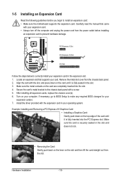
... sure the card is securely seated in your operating system. If necessary, go to BIOS Setup to install an expansion card: • Make sure the motherboard supports the expansion card. Make sure the metal contacts on your computer. Align the card with a screw. 5. 1-5 Installing an Expansion Card Read the following guidelines...
... sure the card is securely seated in your operating system. If necessary, go to BIOS Setup to install an expansion card: • Make sure the motherboard supports the expansion card. Make sure the metal contacts on your computer. Align the card with a screw. 5. 1-5 Installing an Expansion Card Read the following guidelines...
Manual
Page 19
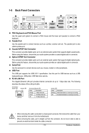
... Data transmission or receiving is occurring Off No data transmission or receiving is also called a printer port. Do not rock it straight out from the motherboard. • When removing the cable, pull it side to side to an external audio system that your audio system provides a coaxial digital audio in connector...
... Data transmission or receiving is occurring Off No data transmission or receiving is also called a printer port. Do not rock it straight out from the motherboard. • When removing the cable, pull it side to side to an external audio system that your audio system provides a coaxial digital audio in connector...
Manual
Page 21
... devices and your devices are compliant with the connectors you wish to connect. • Before installing the devices, be sure to the connector on the motherboard. - 21 - Hardware Installation
... devices and your devices are compliant with the connectors you wish to connect. • Before installing the devices, be sure to the connector on the motherboard. - 21 - Hardware Installation

Manual
Page 22
... the protective cover when using a 2x12 power supply, remove the protective cover from the main power connector on the motherboard. If a power supply is turned off and all the components on the motherboard. When using a 2x10 power supply. 3 4 1 2 ATX_12V ATX_12V: Pin No. 1 2 3 4 Definition GND GND +12V +12V 12 24 1 13 ATX ATX...
... the protective cover when using a 2x12 power supply, remove the protective cover from the main power connector on the motherboard. If a power supply is turned off and all the components on the motherboard. When using a 2x10 power supply. 3 4 1 2 ATX_12V ATX_12V: Pin No. 1 2 3 4 Definition GND GND +12V +12V 12 24 1 13 ATX ATX...

Manual
Page 23
...; These fan headers are : 360 KB, 720 KB, 1.2 MB, 1.44 MB, and 2.88 MB. 3/4/5) CPU_FAN/SYS_FAN1/SYS_FAN2/PWR_FAN (Fan Headers) The motherboard has a 4-pin CPU fan header (CPU_FAN), a 4-pin (SYS_FAN2) and a 3-pin (SYS_FAN1) system fan headers, and a 3-pin power fan header (.../ Speed Control CPU_FAN 3 Sense 4 Speed Control SYS_FAN2: Pin No. Hardware Installation When connecting a fan cable, be installed inside the chassis. The motherboard supports CPU fan speed control, which requires the use of floppy disk drives supported are not configuration jumper blocks. Definition 1 GND 2 +12V 3 ...
...; These fan headers are : 360 KB, 720 KB, 1.2 MB, 1.44 MB, and 2.88 MB. 3/4/5) CPU_FAN/SYS_FAN1/SYS_FAN2/PWR_FAN (Fan Headers) The motherboard has a 4-pin CPU fan header (CPU_FAN), a 4-pin (SYS_FAN2) and a 3-pin (SYS_FAN1) system fan headers, and a 3-pin power fan header (.../ Speed Control CPU_FAN 3 Sense 4 Speed Control SYS_FAN2: Pin No. Hardware Installation When connecting a fan cable, be installed inside the chassis. The motherboard supports CPU fan speed control, which requires the use of floppy disk drives supported are not configuration jumper blocks. Definition 1 GND 2 +12V 3 ...
Manual
Page 26
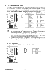
...the pin assignments of the front and back panel audio connections simultaneously. Incorrect connection between the module connector and the motherboard header will be present on each wire instead of a single plug. If you want to mute the back panel... to this header. Definition 1 CD-L 2 GND 3 GND 1 4 CD-R Hardware Installation - 26 - You may connect the audio cable that has separated connectors on both of the motherboard header. Definition 1 2 1 MIC2_L 1 MIC 2 GND 2 GND 9 10 3 MIC2_R 3 MIC Power 4 -ACZ_DET 4 NC 5 LINE2_R 5 Line Out (R) 6 GND 6 NC 7 FAUDIO_JD...
...the pin assignments of the front and back panel audio connections simultaneously. Incorrect connection between the module connector and the motherboard header will be present on each wire instead of a single plug. If you want to mute the back panel... to this header. Definition 1 CD-L 2 GND 3 GND 1 4 CD-R Hardware Installation - 26 - You may connect the audio cable that has separated connectors on both of the motherboard header. Definition 1 2 1 MIC2_L 1 MIC 2 GND 2 GND 9 10 3 MIC2_R 3 MIC Power 4 -ACZ_DET 4 NC 5 LINE2_R 5 Line Out (R) 6 GND 6 NC 7 FAUDIO_JD...
Manual
Page 27
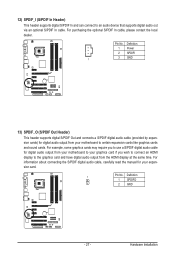
For example, some graphics cards may require you to use a S/PDIF digital audio cable for digital audio output from your motherboard to your graphics card if you wish to connect an HDMI display to the graphics card and have digital audio output from your expansion card... 1 3 GND 13) SPDIF_O (S/PDIF Out Header) This header supports digital S/PDIF Out and connects a S/PDIF digital audio cable (provided by expansion cards) for your motherboard to an audio device that supports digital audio out via an optional S/PDIF In cable. Pin No. For purchasing the optional S/PDIF In cable, please...
For example, some graphics cards may require you to use a S/PDIF digital audio cable for digital audio output from your motherboard to your graphics card if you wish to connect an HDMI display to the graphics card and have digital audio output from your expansion card... 1 3 GND 13) SPDIF_O (S/PDIF Out Header) This header supports digital S/PDIF Out and connects a S/PDIF digital audio cable (provided by expansion cards) for your motherboard to an audio device that supports digital audio out via an optional S/PDIF In cable. Pin No. For purchasing the optional S/PDIF In cable, please...


