
Manual
Page 4
Table of Contents Box Contents ...6 OptionalItems...6 GA-EP35-DS4 Motherboard Layout 7 Block Diagram...8 Chapter 1 Hardware Installation 9 1-1 Installation Precautions 9 1-2 Product Specifications 10 1-3 Installing the CPU and CPU Cooler 13 1-3-1 Installing the CPU 13 1-3-2 Installing the CPU Cooler 15 1-4 Installing the Memory 16 1-4-1 Dual Channel Memory Configuration 16 1-4-2 Installing a Memory 17 1-5 Installing an Expansion Card 18 1-6 Installing the SATA Bracket...
Table of Contents Box Contents ...6 OptionalItems...6 GA-EP35-DS4 Motherboard Layout 7 Block Diagram...8 Chapter 1 Hardware Installation 9 1-1 Installation Precautions 9 1-2 Product Specifications 10 1-3 Installing the CPU and CPU Cooler 13 1-3-1 Installing the CPU 13 1-3-2 Installing the CPU Cooler 15 1-4 Installing the Memory 16 1-4-1 Dual Channel Memory Configuration 16 1-4-2 Installing a Memory 17 1-5 Installing an Expansion Card 18 1-6 Installing the SATA Bracket...

Manual
Page 6
...-01R) COM port cable (Part No. 12CF1-1CM001-32R) LPT port cable (Part No. 12CF1-1LP001-01R) - 6 - Box Contents GA-EP35-DS4 motherboard Motherboard driver disk User's Manual Quick Installation Guide Intel® LGA775 CPU Installation Guide One IDE cable and one floppy disk drive cable Four SATA 3Gb/s cables One SATA bracket I/O Shield...
...-01R) COM port cable (Part No. 12CF1-1CM001-32R) LPT port cable (Part No. 12CF1-1LP001-01R) - 6 - Box Contents GA-EP35-DS4 motherboard Motherboard driver disk User's Manual Quick Installation Guide Intel® LGA775 CPU Installation Guide One IDE cable and one floppy disk drive cable Four SATA 3Gb/s cables One SATA bracket I/O Shield...

Manual
Page 8
... MHz) LAN RJ45 x1 x1 x1 Switch RTL8111B x1 PCI Express Bus 2 SATA 3Gb/s ATA-133/100/66/ 33 IDE Channel GIGABYTE SATA2 PCI Bus TSB43AB23 3 IEEE 1394a LGA775 Processor CPU CLK+/(400 (O.C.)/333/266/200 MHz) Host Interface DDR2 1200 (O.C.)/1066/ 800/667 MHz Intel® P35 Dual Channel Memory MCH...
... MHz) LAN RJ45 x1 x1 x1 Switch RTL8111B x1 PCI Express Bus 2 SATA 3Gb/s ATA-133/100/66/ 33 IDE Channel GIGABYTE SATA2 PCI Bus TSB43AB23 3 IEEE 1394a LGA775 Processor CPU CLK+/(400 (O.C.)/333/266/200 MHz) Host Interface DDR2 1200 (O.C.)/1066/ 800/667 MHz Intel® P35 Dual Channel Memory MCH...

Manual
Page 9
.... • Prior to installing the motherboard, please have a problem related to wear an electrostatic discharge (ESD) wrist strap when handling electronic components such as a motherboard, CPU or memory.
.... • Prior to installing the motherboard, please have a problem related to wear an electrostatic discharge (ESD) wrist strap when handling electronic components such as a motherboard, CPU or memory.

Manual
Page 10
... PCI Express x1 slots (share with CPU Š 1600 (O.C.)/1333/1066/800 MHz FSB Š North Bridge: Intel® P35 Chipset Š South Bridge: Intel® ICH9R Š 4 x 1.8V DDR2 DIMM sockets supporting up to the internal IEEE 1394 header) GA-EP35-DS4 Motherboard - 10 - TSB43AB23 chip Š... system memory (Note 1) Š Dual channel memory architecture Š Support for DDR2 1200 (O.C.)/1066/800/667 MHz memory modules (Go to GIGABYTE's website for the latest memory support list.) Š Realtek ALC889A codec Š High Definition Audio Š 2/4/5.1/7.1-channel Š Support for ...
... PCI Express x1 slots (share with CPU Š 1600 (O.C.)/1333/1066/800 MHz FSB Š North Bridge: Intel® P35 Chipset Š South Bridge: Intel® ICH9R Š 4 x 1.8V DDR2 DIMM sockets supporting up to the internal IEEE 1394 header) GA-EP35-DS4 Motherboard - 10 - TSB43AB23 chip Š... system memory (Note 1) Š Dual channel memory architecture Š Support for DDR2 1200 (O.C.)/1066/800/667 MHz memory modules (Go to GIGABYTE's website for the latest memory support list.) Š Realtek ALC889A codec Š High Definition Audio Š 2/4/5.1/7.1-channel Š Support for ...

Manual
Page 11
...138; 1 x 4-pin PCIe 12V power connector Š 1 x floppy disk drive connector Š 1 x IDE connector Š 8 x SATA 3Gb/s connectors Š 1 x CPU fan header Š 2 x system fan headers Š 1 x power fan header Š 1 x North Bridge fan header Š 1 x front panel header Š 1 ... iTE IT8718 chip Hardware Monitor Š System voltage detection Š CPU/System temperature detection Š CPU/System/Power fan speed detection Š CPU overheating warning Š CPU/System/Power fan fail warning Š CPU fan speed control(Note 3) - 11 - Hardware Installation
...138; 1 x 4-pin PCIe 12V power connector Š 1 x floppy disk drive connector Š 1 x IDE connector Š 8 x SATA 3Gb/s connectors Š 1 x CPU fan header Š 2 x system fan headers Š 1 x power fan header Š 1 x North Bridge fan header Š 1 x front panel header Š 1 ... iTE IT8718 chip Hardware Monitor Š System voltage detection Š CPU/System temperature detection Š CPU/System/Power fan speed detection Š CPU overheating warning Š CPU/System/Power fan fail warning Š CPU fan speed control(Note 3) - 11 - Hardware Installation

Manual
Page 12
...MHz increment Š Support for Dynamic Energy Saver Š Norton Internet Security (OEM version) Š Voltage adjustments in BIOS Setup (CPU/DDR2/PCIe/FSB/(G)MCH) allow you to: - Adjust DDR2 frequency - Adjust PCI Express frequency from 100 MHz to 700 MHz with ...allow you to: - Increase PCIe voltage by 0.025V to 0.375V with 1 MHz increment - Adjust CPU host frequency from 90 MHz to 150 MHz with 0.05V increment - GA-EP35-DS4 Motherboard - 12 - Increase CPU voltage (Note 5) - BIOS Unique Features Bundled Software Overclocking Operating System Form Factor Š 2 x...
...MHz increment Š Support for Dynamic Energy Saver Š Norton Internet Security (OEM version) Š Voltage adjustments in BIOS Setup (CPU/DDR2/PCIe/FSB/(G)MCH) allow you to: - Adjust DDR2 frequency - Adjust PCI Express frequency from 100 MHz to 700 MHz with ...allow you to: - Increase PCIe voltage by 0.025V to 0.375V with 1 MHz increment - Adjust CPU host frequency from 90 MHz to 150 MHz with 0.05V increment - GA-EP35-DS4 Motherboard - 12 - Increase CPU voltage (Note 5) - BIOS Unique Features Bundled Software Overclocking Operating System Form Factor Š 2 x...

Manual
Page 13
... cord from the power outlet before installing the CPU to prevent hardware damage. • Locate the pin one of the CPU Socket Notch Notch Triangle Pin One Marking on the CPU. mended that the motherboard supports the CPU. (Go to GIGABYTE's website for the peripherals. 1-3 Installing the CPU and CPU Cooler Read the following guidelines before you...
... cord from the power outlet before installing the CPU to prevent hardware damage. • Locate the pin one of the CPU Socket Notch Notch Triangle Pin One Marking on the CPU. mended that the motherboard supports the CPU. (Go to GIGABYTE's website for the peripherals. 1-3 Installing the CPU and CPU Cooler Read the following guidelines before you...

Manual
Page 14
... its locked position. Step 5: Once the CPU is properly inserted, replace the load plate and push the CPU socket lever back into position. CPU Socket Lever Step 1: Completely raise the CPU socket lever. Step 3: Lift the metal load plate on the CPU socket. GA-EP35-DS4 Motherboard - 14 - Align the CPU pin one marking (triangle) with the pin one...
... its locked position. Step 5: Once the CPU is properly inserted, replace the load plate and push the CPU socket lever back into position. CPU Socket Lever Step 1: Completely raise the CPU socket lever. Step 3: Lift the metal load plate on the CPU socket. GA-EP35-DS4 Motherboard - 14 - Align the CPU pin one marking (triangle) with the pin one...

Manual
Page 15
... the four push pins through the pin holes on the surface of the motherboard. 1-3-2 Installing the CPU Cooler Follow the steps below to correctly install the CPU cooler on the motherboard. (The following procedure uses Intel® boxed cooler as the picture above, the installation is complete.... You should hear a "click" when pushing down on the motherboard. Use extreme care when removing the CPU cooler because the thermal grease/tape between the CPU cooler and CPU may damage the CPU. - 15 - Hardware Installation Check that the Male and Female push pins are joined closely. (Refer ...
... the four push pins through the pin holes on the surface of the motherboard. 1-3-2 Installing the CPU Cooler Follow the steps below to correctly install the CPU cooler on the motherboard. (The following procedure uses Intel® boxed cooler as the picture above, the installation is complete.... You should hear a "click" when pushing down on the motherboard. Use extreme care when removing the CPU cooler because the thermal grease/tape between the CPU cooler and CPU may damage the CPU. - 15 - Hardware Installation Check that the Male and Female push pins are joined closely. (Refer ...

Manual
Page 23
... connector in the correct orientation. If a power supply is turned off and all the components on the motherboard. Connect the power supply cable to the CPU. When using a power supply providing a 2x2 12V and a 2x10 power connector. 8 4 5 1 ATX_12V_2X ATX_12V_2X: Pin No. Before connecting the power connector,... 3.3V 14 GND 15 +5V 16 GND 17 +5V 18 GND 19 Power Good 20 5V SB(stand by the CPU manufacturer when using an Intel Extreme Edition CPU (130W). • To meet expansion requirements, it is recommended that a power supply that does not provide the required power...
... connector in the correct orientation. If a power supply is turned off and all the components on the motherboard. Connect the power supply cable to the CPU. When using a power supply providing a 2x2 12V and a 2x10 power connector. 8 4 5 1 ATX_12V_2X ATX_12V_2X: Pin No. Before connecting the power connector,... 3.3V 14 GND 15 +5V 16 GND 17 +5V 18 GND 19 Power Good 20 5V SB(stand by the CPU manufacturer when using an Intel Extreme Edition CPU (130W). • To meet expansion requirements, it is recommended that a power supply that does not provide the required power...

Manual
Page 24
Failure to do so may lead to this connector when using two graphics cards. The higher the CPU loading, the more the number of lighted LEDs indicates the CPU loading. GA-EP35-DS4 Motherboard - 24 - Definition 1 NC 2 GND 3 GND 4 +12V 4) PHASE LED The number of lighted LEDs. Connect the power supply cable to an unstable system. 1 PIin No. 3) PCIE_12V (Power Connector) This power connector can supply extra power to the PCI Express x16 slots on the motherboard.
Failure to do so may lead to this connector when using two graphics cards. The higher the CPU loading, the more the number of lighted LEDs indicates the CPU loading. GA-EP35-DS4 Motherboard - 24 - Definition 1 NC 2 GND 3 GND 4 +12V 4) PHASE LED The number of lighted LEDs. Connect the power supply cable to an unstable system. 1 PIin No. 3) PCIE_12V (Power Connector) This power connector can supply extra power to the PCI Express x16 slots on the motherboard.

Manual
Page 25
... CPU_FAN: 1 Pin No. Most fans are not configuration jumper blocks. Pin No. 5/6/7) CPU_FAN/SYS_FAN1/SYS_FAN2/PWR_FAN (Fan Headers) The motherboard has a 4-pin CPU fan header (CPU_FAN), a 3-pin (SYS_FAN1) and a 4-pin (SYS_FAN2) system fan headers, and a 3-pin power fan header (PWR_FAN). Each fan header ...Bridge Fan Header) 2 +12V 3 Sense Connect the North Bridge fan cable to prevent your CPU, North Bridge and system from overheating. When connecting a fan cable, be sure to the CPU/North Bridge or the system may result in damage to connect it in the correct orientation....
... CPU_FAN: 1 Pin No. Most fans are not configuration jumper blocks. Pin No. 5/6/7) CPU_FAN/SYS_FAN1/SYS_FAN2/PWR_FAN (Fan Headers) The motherboard has a 4-pin CPU fan header (CPU_FAN), a 3-pin (SYS_FAN1) and a 4-pin (SYS_FAN2) system fan headers, and a 3-pin power fan header (PWR_FAN). Each fan header ...Bridge Fan Header) 2 +12V 3 Sense Connect the North Bridge fan cable to prevent your CPU, North Bridge and system from overheating. When connecting a fan cable, be sure to the CPU/North Bridge or the system may result in damage to connect it in the correct orientation....

Manual
Page 38
...to 8 profiles (Profile 1-8) and name each profile. First enter the profile name (to erase the default profile name, use this task.) GA-EP35-DS4 Motherboard - 38 - It allows you to view the BIOS settings but not to make changes in the BIOS Setup program to the confirmation message...Use this menu to configure the system's PCI & PnP resources. „ PC Health Status Use this menu to see information about autodetected system/CPU temperature, system voltage and fan speed, etc. „ MB Intelligent Tweaker(M.I.T.) Use this task.) „ Exit Without Saving Abandon all the ...
...to 8 profiles (Profile 1-8) and name each profile. First enter the profile name (to erase the default profile name, use this task.) GA-EP35-DS4 Motherboard - 38 - It allows you to view the BIOS settings but not to make changes in the BIOS Setup program to the confirmation message...Use this menu to configure the system's PCI & PnP resources. „ PC Health Status Use this menu to see information about autodetected system/CPU temperature, system voltage and fan speed, etc. „ MB Intelligent Tweaker(M.I.T.) Use this task.) „ Exit Without Saving Abandon all the ...

Manual
Page 41
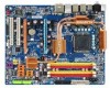
...password is required for booting the system and for entering the BIOS Setup program. to 3 (Note) No-Execute Memory Protect (Note) CPU Enhanced Halt (C1E) (Note) CPU Thermal Monitor 2(TM2) (Note) CPU EIST Function (Note) Virtualization Technology (Note) Full Screen LOGO Show Init Display First [Press Enter] [Floppy] [Hard Disk] [... for entering the BIOS Setup program. (Default) A password is required every time the system boots, or only when you install a CPU that supports this item, set the password(s) under the Set Supervisor/User Password item in the BIOS Main Menu. HDD S.M.A.R.T.
...password is required for booting the system and for entering the BIOS Setup program. to 3 (Note) No-Execute Memory Protect (Note) CPU Enhanced Halt (C1E) (Note) CPU Thermal Monitor 2(TM2) (Note) CPU EIST Function (Note) Virtualization Technology (Note) Full Screen LOGO Show Init Display First [Press Enter] [Floppy] [Hard Disk] [... for entering the BIOS Setup program. (Default) A password is required every time the system boots, or only when you install a CPU that supports this item, set the password(s) under the Set Supervisor/User Password item in the BIOS Main Menu. HDD S.M.A.R.T.
Manual
Page 42
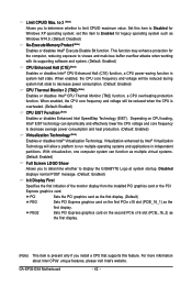
... LOGO Show Allows you to determine whether to display the GIGABYTE Logo at system startup. For more information about Intel CPUs' unique features, please visit Intel's website. When enabled, the CPU core frequency and voltage will allow a platform to Enabled for...Technology (Note) Enables or disables Intel® Virtualization Technology. GA-EP35-DS4 Motherboard - 42 - Depending on CPU loading, Intel® EIST technology can function as the first display. (Note) This item is overheated. (Default: Enabled) CPU EIST Function (Note) Enables or disables Enhanced Intel SpeedStep ...
... LOGO Show Allows you to determine whether to display the GIGABYTE Logo at system startup. For more information about Intel CPUs' unique features, please visit Intel's website. When enabled, the CPU core frequency and voltage will allow a platform to Enabled for...Technology (Note) Enables or disables Intel® Virtualization Technology. GA-EP35-DS4 Motherboard - 42 - Depending on CPU loading, Intel® EIST technology can function as the first display. (Note) This item is overheated. (Default: Enabled) CPU EIST Function (Note) Enables or disables Enhanced Intel SpeedStep ...

Manual
Page 49
...Case Open Status Case Opened Vcore DDR18V +3.3V +12V Current System Temperature Current CPU Temperature Current CPU FAN Speed Current SYSTEM FAN2 Speed Current POWER FAN Speed Current SYSTEM FAN1 Speed CPU Warning Temperature CPU FAN Fail Warning SYSTEM FAN2 Fail Warning POWER FAN Fail Warning SYSTEM FAN1 ...or clears the record of previous chassis intrusion status and the Case Opened field will emit warning sound. When CPU temperature exceeds the threshold, BIOS will show "No". CPU/SYSTEM/POWER FAN Fail Warning Allows the system to CMOS, and then restart your system. BIOS Setup If...
...Case Open Status Case Opened Vcore DDR18V +3.3V +12V Current System Temperature Current CPU Temperature Current CPU FAN Speed Current SYSTEM FAN2 Speed Current POWER FAN Speed Current SYSTEM FAN1 Speed CPU Warning Temperature CPU FAN Fail Warning SYSTEM FAN2 Fail Warning POWER FAN Fail Warning SYSTEM FAN1 ...or clears the record of previous chassis intrusion status and the Case Opened field will emit warning sound. When CPU temperature exceeds the threshold, BIOS will show "No". CPU/SYSTEM/POWER FAN Fail Warning Allows the system to CMOS, and then restart your system. BIOS Setup If...

Manual
Page 50
...pin CPU fan that is set for a 3-pin CPU fan. Enabled allows the CPU fan to run at full speed. (Default: Enabled) CPU Smart FAN Mode Specifies how to control CPU fan speed. If disabled, CPU fan runs at different speed according to Enabled. However, for a 4-pin CPU fan. GA-EP35-DS4 ...Motherboard - 50 - Note: The Voltage mode can adjust the fan speed with EasyTune based on system requirements. Auto Lets BIOS autodetect the type of CPU fan installed and sets the optimal CPU fan control mode. (Default) Voltage...
...pin CPU fan that is set for a 3-pin CPU fan. Enabled allows the CPU fan to run at full speed. (Default: Enabled) CPU Smart FAN Mode Specifies how to control CPU fan speed. If disabled, CPU fan runs at different speed according to Enabled. However, for a 4-pin CPU fan. GA-EP35-DS4 ...Motherboard - 50 - Note: The Voltage mode can adjust the fan speed with EasyTune based on system requirements. Auto Lets BIOS autodetect the type of CPU fan installed and sets the optimal CPU fan control mode. (Default) Voltage...

Manual
Page 51
...(M.I.T.) CMOS Setup Utility-Copyright (C) 1984-2007 Award Software MB Intelligent Tweaker(M.I.T.) Robust Graphics Booster CPU Clock Ratio (Note) CPU Frequency CPU Host Clock Control x CPU Host Frequency (Mhz) PCI Express Frequency (Mhz) C.I.A. 2 Performance Enhance System Memory Multiplier ...System Voltage Optimized System Voltage Control DDR2 OverVoltage Control PCI-E OverVoltage Control FSB OverVoltage Control (G)MCH OverVoltage Control Loadline Calibration CPU Voltage Control Normal CPU Vcore 4 20 2 4 13 ******** Auto Auto Auto Auto Auto [Manual] [Normal] [Normal] [Normal] [...
...(M.I.T.) CMOS Setup Utility-Copyright (C) 1984-2007 Award Software MB Intelligent Tweaker(M.I.T.) Robust Graphics Booster CPU Clock Ratio (Note) CPU Frequency CPU Host Clock Control x CPU Host Frequency (Mhz) PCI Express Frequency (Mhz) C.I.A. 2 Performance Enhance System Memory Multiplier ...System Voltage Optimized System Voltage Control DDR2 OverVoltage Control PCI-E OverVoltage Control FSB OverVoltage Control (G)MCH OverVoltage Control Loadline Calibration CPU Voltage Control Normal CPU Vcore 4 20 2 4 13 ******** Auto Auto Auto Auto Auto [Manual] [Normal] [Normal] [Normal] [...

Manual
Page 52
... to 400 MHz. mode based on CPU loading. The item is present only if a CPU with the CPU specifications. CPU Frequency Displays the current operating CPU frequency. Note: If your system hardware components. The adjustable range is installed. Sports Increases CPU frequency by 7% or 9% depending on system configurations. GA-EP35-DS4 Motherboard - 52 - CPU Clock Ratio (Note) Allows you to...
... to 400 MHz. mode based on CPU loading. The item is present only if a CPU with the CPU specifications. CPU Frequency Displays the current operating CPU frequency. Note: If your system hardware components. The adjustable range is installed. Sports Increases CPU frequency by 7% or 9% depending on system configurations. GA-EP35-DS4 Motherboard - 52 - CPU Clock Ratio (Note) Allows you to...


