
Manual
Page 10
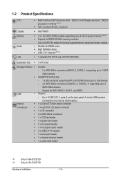
Support for GA-D425TUD. k Only for SATA RAID 0, RAID 1, and JBOD USB Chipset: - Hardware Installation - 10 - Up...1 x PCI slot Storage Interface Chipset: - 2 x SATA 3Gb/s connectors (SATA2_0, SATA2_1) supporting up to 2 SATA 3Gb/s devices GIGABYTE SATA2 chip: - 1 x IDE connector supporting ATA-133/100/66/33 and up to 2 IDE devices - 2 x SATA 3Gb/s connectors (GSATA2_0, GSATA2_1...(Note 1) 1M L2 cachej/512K L2 cachek Intel® NM10 2 x 1.5V DDR3 DIMM sockets supporting up to GIGABYTE's website for GA-D525TUD.
Support for GA-D425TUD. k Only for SATA RAID 0, RAID 1, and JBOD USB Chipset: - Hardware Installation - 10 - Up...1 x PCI slot Storage Interface Chipset: - 2 x SATA 3Gb/s connectors (SATA2_0, SATA2_1) supporting up to 2 SATA 3Gb/s devices GIGABYTE SATA2 chip: - 1 x IDE connector supporting ATA-133/100/66/33 and up to 2 IDE devices - 2 x SATA 3Gb/s connectors (GSATA2_0, GSATA2_1...(Note 1) 1M L2 cachej/512K L2 cachek Intel® NM10 2 x 1.5V DDR3 DIMM sockets supporting up to GIGABYTE's website for GA-D525TUD.
Manual
Page 12
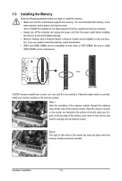
... have a foolproof design. Step 1: Note the orientation of the memory, push down on the memory and insert it can be used. (Go to GIGABYTE's website for the latest supported memory speeds and memory modules.) • Always turn off the computer and unplug the power cord from the power outlet... be installed in the picture on the left, place your memory modules in one direction. Step 2: The clips at both ends of the socket will snap into the memory socket. As indicated in only one direction. It is securely inserted. If you begin to correctly install your fingers on the...
... have a foolproof design. Step 1: Note the orientation of the memory, push down on the memory and insert it can be used. (Go to GIGABYTE's website for the latest supported memory speeds and memory modules.) • Always turn off the computer and unplug the power cord from the power outlet... be installed in the picture on the left, place your memory modules in one direction. Step 2: The clips at both ends of the socket will snap into the memory socket. As indicated in only one direction. It is securely inserted. If you begin to correctly install your fingers on the...
Manual
Page 79
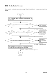
... is verified and solved. Is the power connector of the CPU cooler connected to solve the problem. No Correctly insert the memory into the memory socket. Insert the graphics card. START Turn off the power. A (Continued...) - 79 - Connect the CPU cooler power cable to start the computer. Secure the CPU cooler...
... is verified and solved. Is the power connector of the CPU cooler connected to solve the problem. No Correctly insert the memory into the memory socket. Insert the graphics card. START Turn off the power. A (Continued...) - 79 - Connect the CPU cooler power cable to start the computer. Secure the CPU cooler...
Manual
Page 80
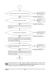
.... The problem is verified and solved. Check if the system can boot successfully. Yes Reinstall the operating system. No The power supply, CPU or CPU socket might fail.
.... The problem is verified and solved. Check if the system can boot successfully. Yes Reinstall the operating system. No The power supply, CPU or CPU socket might fail.

