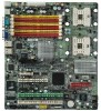
User Manual
Page 1
GA-9IVDT Dual XeonTM (Nocona/Iwindale) Processor Motherboard USER'S MANUAL Dual XeonTM (Nocona/Iwindale)Processor Motherboard Rev. 1102 12ME-9IVDT-1102
User Manual
Page 2
... Table of Content Item Checklist 4 WARNING 4 Chapter 1 Introduction 5 Features Summary 5 GA-9IVDT Motherboard Layout 7 Chapter 2 Hardware Installation Process 9 Step 1: Install the Central Processing Unit (CPU 10 Step 1-2:CPU Heat Sink Installation 11 Step 2: Install memory modules 13 ...
User Manual
Page 4
...touch the IC chips, leads or connectors, or other components. 4. Ensure that are no slots to the chassis... English GA-9IVDTMotherboard Item Checklist The GA-9IVDT motherboard Printer Port (LPT) cable x 1 IDE to the base without worrying about short circuits. Use a grounded wrist strap...cable x 2 CD for motherboard driver & utility I/O Shield x1 Serial ATA cable x 4 PATA ( 1 cables) & FDD cable set x 1 GA-9IVDT quick installation guide GA-9IVDT user's manual Retention Module x 2 WARNING! Installing the motherboard to attach the spacers, do not have one, touch both of your hands to a...
User Manual
Page 5
... (5V) y 1 PCI-E slot by cable) y 1 x VGA port y 2 x RJ45 LAN port Hardware Monitor y CPU/Power/System Fan Revolution Detect y CPU shutdown when overtemperature y System Voltage Detect 5 y GA-9IVDT Motherboard: CPU Chipset Memory I/O Control Slots On-Board IDE y Dual socket 604 for up to 2 ATAPI devices On-Board Peripherals y 1 Floppy port supports 2 FDD with...
User Manual
Page 6
English GA-9IVDTMotherboard SATA Controller On-Board SATA RAID y Adaptec® AIC-8130 chipset supports SATAII 4 ports y Supports RAID 0 ,1, 5, 10 with ZCR card (2020s) y Supports HOST RAID (...
User Manual
Page 7
GA-9IVDT Motherboard Layout O N M S L KJ I V T 㕼㕧 㖅㕧 㕺㖀㕣 㖅㖃㕲㕢 W 㖅㕡 㕼㕡 㖅㕧 㕼㕧 E X 㖅㕡 㕼...
User Manual
Page 8
G_LAN2 (LAN1 Port) D. FDD1 (Floppy Connector) 8. DDR5 L. DDR4 M. COM2 15. English GA-9IVDTMotherboard A. Intel E7320 3. Adaptec AIC-8130 5. ATX1Power connector) V. PCI1 Z. CPU1 (Install First) 1. Intel 6300ESB 4. VGA1 (VGA Port) F. KB_MS (Keyboard & Mouse) J. DDR3 N. F_Panel1(Front Panel) 14. ...
User Manual
Page 10
... socket and look for a (golden) cut edge well, it will cause improper installation. Press down the CPU socket lever and finish CPU installation. 10 English GA-9IVDTMotherboard Step 1: Install the Central Processing Unit (CPU) Before installing the processor , adhere to 90-degree when a noise "cough" made. Angling the rod to 65...
User Manual
Page 12
Make sure the CPU fan is plugged to the CPU fan connector, than install complete. 12 Fasten the heatsink supporting-base onto the CPU socket on the mainboard. 4. English GA-9IVDTMotherboard 3.
User Manual
Page 14
English GA-9IVDTMotherboard 1. The DIMM slot has a notch, so the DIMM memory module can only fit in order starting at both edges of the DIMM slots to remove the DIMM module. Insert the DIMM memory module vertically into the DIMM slot. Please note that DIMM must be populated in one direction. 2. Notch 14 Close the plastic clip at the nearest slot from the ATX power. 3. Then push it down. Reverse the installation steps when you wish to lock the DIMM module.
User Manual
Page 15
... Rank 15 Supported DIMM Module Type Technology 256MB 512MB 1GB Organization 8MB x 8 x 4 bks 16MB x 4 x 4bks 16MB x 8 x 4bks 32MB x 4 x 4bks 32MB x 8 x 4bks 64MB x 4 x 4bks Table 2. English GA-9IVDTMotherboard Table 1.
User Manual
Page 17
\ \ [ 17 GA-9IVDTMotherboard Step 4: Connect ribbon cables, cabinet wires, and power supply Step 4-1 : I/O Back Panel Introduction 㕺㖀㕣 㖅㖃㕲㕢 㕢 㕹㕴㕵...
User Manual
Page 19
English GA-9IVDTMotherboard Step 4-2 :Connectors and Jumper Setting Introduction J IT Q P D G R 1 V H 㕺㖀㕣 㖅㖃㕲㕢 㕼㖀㖄㕡 㖇㕿㖂㕡 㖇㕿...
User Manual
Page 21
...;㕡 㕼㕧 㕼㕡 㕼㕧 㕼㕡 㕼㕧 㕼㕡 㕼㕧 㕼㕡 㕴㕴㖂㕡 33 34 21 English GA-9IVDTMotherboard C) IDE1 Connector Please connect first harddisk to FDD.
User Manual
Page 23
English GA-9IVDTMotherboard H ) USB2 (Front USB Connector ) Be careful with the polarity of the front USB connector. Check the pin assignment while you connect the front USB ...
User Manual
Page 24
...;㕿㖂㕡 㕺㖀㕣 㖅㖃㕲㕢 㖇㕿㕼㕡 㕳㖀㖅㕡 㕴㕴㖂㕡 Pin No. English GA-9IVDTMotherboard J ) WOL1 (Wake on LAN) This connector allows the remove servers to prevent the CPU from running under abnormal condition or damaged by overheating.The...
User Manual
Page 25
English GA-9IVDTMotherboard M) PWR_FAN1 (Power Fan Connector) This connector allows you to link with the cooling fan on the system case to lower the system temperature. 㕼...
User Manual
Page 27
... ID LED Switch Case Open Signal Service ID LED Switch GND LAN2 access LED Signal NMI Switch cathode(-) LAN2 linked LED Signal cathode(-) 27 English GA-9IVDTMotherboard R ) F_Panel1 ( 2 x 12 pins connector) &Please connect the power LED, PC speaker, reset switch and power switch of your chassis front panel to the F_PANEL...
User Manual
Page 28
... if battery is incorrectly replaced. Replace only with the same or equivalent type recommended by the manufacturer. If you want to the manufacturer's instructions. English GA-9IVDTMotherboard S ) BAT1 (Battery) 㕳㕿㕽㕡 㖅㖃㕲㕡 㕴㕴㖂㕢 㕼㖀㖄㕡 㕱㖄㖈㕡 㖇㕿...
User Manual
Page 32
... modify the basic system configuration. Exit current page and return to the item in battery-backed CMOS RAM so that allows users to enter Setup. GA-9IVDT Motherboard Chapter 3 BIOS Setup BIOS Setup is an overview of information is stored in the right hand Main Menu - Quit and not save changes into...