
Manual
Page 4
Table of Contents ItemChecklist ...6 OptionalAccessories ...6 GA-965P-DS4 Motherboard Layout 7 Block Diagram ...8 Chapter 1 Hardware Installation 9 1-1 Considerations Prior to Installation 9 1-2 Feature Summary 10 1-3 Installation of the CPU and CPU Cooler 13 1-3-1 Installation of the CPU 13 1-3-2 Installation of the CPU Cooler 14 1-4 Installation of Memory 15 1-5 Installation of Expansion Cards 17 1-6 I/O Back Panel Introduction 18 1-7 Connectors Introduction 19 Chapter...
Table of Contents ItemChecklist ...6 OptionalAccessories ...6 GA-965P-DS4 Motherboard Layout 7 Block Diagram ...8 Chapter 1 Hardware Installation 9 1-1 Considerations Prior to Installation 9 1-2 Feature Summary 10 1-3 Installation of the CPU and CPU Cooler 13 1-3-1 Installation of the CPU 13 1-3-2 Installation of the CPU Cooler 14 1-4 Installation of Memory 15 1-5 Installation of Expansion Cards 17 1-6 I/O Back Panel Introduction 18 1-7 Connectors Introduction 19 Chapter...
Manual
Page 8
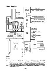
... MHz) x1 x1 x1 Switch LAN RJ45 Marvell 8056 x1 PCI Express Bus 2 SATA 3Gb/s ATA-33/66/100/ 133 IDE Channel PCI Bus GIGABYTE SATA2 LGA775 Processor CPU CLK+/(333(Note 1)/266/200/133 MHz) Host Interface DDRII 800/667/533 MHz DIMM(Note 2) Intel® P965 Dual Channel Memory MCH.../Subwoofer Speaker Out Side Speaker Out MIC Line-Out Line-In SPDIF In SPDIF Out 2 PCI PCI CLK (33 MHz) (Note 1) Applies only when the GA-965P-DS4 motherboard (rev. 3.3) is installed.
... MHz) x1 x1 x1 Switch LAN RJ45 Marvell 8056 x1 PCI Express Bus 2 SATA 3Gb/s ATA-33/66/100/ 133 IDE Channel PCI Bus GIGABYTE SATA2 LGA775 Processor CPU CLK+/(333(Note 1)/266/200/133 MHz) Host Interface DDRII 800/667/533 MHz DIMM(Note 2) Intel® P965 Dual Channel Memory MCH.../Subwoofer Speaker Out Side Speaker Out MIC Line-Out Line-In SPDIF In SPDIF Out 2 PCI PCI CLK (33 MHz) (Note 1) Applies only when the GA-965P-DS4 motherboard (rev. 3.3) is installed.

Manual
Page 9
... or within a electrostatic shielding container. 5. Product determined to installation, please follow the instructions below: 1. Thus, prior to be an unofficial Gigabyte product. - 9 - It is switched off the computer and unplug its components. 5. Before using the product, please verify that the power... supply is best to wear an electrostatic discharge (ESD) cuff when handling electronic components (CPU, RAM). 4. If you are required for warranty validation. 2. Please verify that all cables and power connectors are no leftover...
... or within a electrostatic shielding container. 5. Product determined to installation, please follow the instructions below: 1. Thus, prior to be an unofficial Gigabyte product. - 9 - It is switched off the computer and unplug its components. 5. Before using the product, please verify that the power... supply is best to wear an electrostatic discharge (ESD) cuff when handling electronic components (CPU, RAM). 4. If you are required for warranty validation. 2. Please verify that all cables and power connectors are no leftover...

Manual
Page 10
... RAID 0, RAID 1, RAID 5, and RAID 10 for Serial ATA Š GIGABYTE SATA2 Controller - 1 IDE connectors with CPU Š Supports 1333(Note 1)/1066/800/533 MHz FSB Š Northbridge: ... SATA 3Gb/s connectors (SATAII0, SATAII1, SATAII2, SATAII3, SATAII4, SATAII5), allowing connection of 2 SATA 3Gb/s devices - English 1-2 Feature Summary CPU Front Side Bus Chipset LAN Audio IEEE 1394 Storage O.S Support Memory Expanstion Slots Š LGA775 for Intel® CoreTM 2 Extreme quad-core... the same PCIe bus with the PCIE_16_2 slot) (Note 3) Š 2 PCI slots GA-965P-DS4 Motherboard - 10 -
... RAID 0, RAID 1, RAID 5, and RAID 10 for Serial ATA Š GIGABYTE SATA2 Controller - 1 IDE connectors with CPU Š Supports 1333(Note 1)/1066/800/533 MHz FSB Š Northbridge: ... SATA 3Gb/s connectors (SATAII0, SATAII1, SATAII2, SATAII3, SATAII4, SATAII5), allowing connection of 2 SATA 3Gb/s devices - English 1-2 Feature Summary CPU Front Side Bus Chipset LAN Audio IEEE 1394 Storage O.S Support Memory Expanstion Slots Š LGA775 for Intel® CoreTM 2 Extreme quad-core... the same PCIe bus with the PCIE_16_2 slot) (Note 3) Š 2 PCI slots GA-965P-DS4 Motherboard - 10 -

Manual
Page 11
... connector Š 1 4-pin PCIe 12V power connector Š 1 floppy connector Š 1 IDE connector Š 8 SATA 3Gb/s connectors Š 1 CPU fan connector Š 1 system fan connector Š 1 power fan connector Š 1 front panel connector Š 1 front audio connector Š 1...; IT8718 chip Hardware Monitor Š System voltage detection Š CPU / System temperature detection Š CPU / System / Power fan speed detection Š CPU warning temperature Š CPU / System / Power fan failure warning Š CPU smart fan control BIOS Š 2 8 Mbit flash ROM &#...
... connector Š 1 4-pin PCIe 12V power connector Š 1 floppy connector Š 1 IDE connector Š 8 SATA 3Gb/s connectors Š 1 CPU fan connector Š 1 system fan connector Š 1 power fan connector Š 1 front panel connector Š 1 front audio connector Š 1...; IT8718 chip Hardware Monitor Š System voltage detection Š CPU / System temperature detection Š CPU / System / Power fan speed detection Š CPU warning temperature Š CPU / System / Power fan failure warning Š CPU smart fan control BIOS Š 2 8 Mbit flash ROM &#...

Manual
Page 12
...05V to 0.75V) - Adjustable FSB/ DDRII frequencies Form Factor Š ATX form factor; 30.5cm x 24.4cm (Note 1) Applies only when the GA-965P-DS4 motherboard (rev. 3.3) is dependent on processors. PCI Express x16 Frequency : Allows 1 MHz increment from 0.05V to 0.775V) - DIMM Over Voltage :...x1 slots will automatically adjust BIOS to 150 MHz - CPU Over Voltage : Adjustable CPU voltage at 0.05V (Adjustable range from 90 MHz to support 1333 MHz FSB by overclocking when a 1333 MHz FSB processor is installed. GA-965P-DS4 Motherboard - 12 - The system will be unavailable when...
...05V to 0.75V) - Adjustable FSB/ DDRII frequencies Form Factor Š ATX form factor; 30.5cm x 24.4cm (Note 1) Applies only when the GA-965P-DS4 motherboard (rev. 3.3) is dependent on processors. PCI Express x16 Frequency : Allows 1 MHz increment from 0.05V to 0.775V) - DIMM Over Voltage :...x1 slots will automatically adjust BIOS to 150 MHz - CPU Over Voltage : Adjustable CPU voltage at 0.05V (Adjustable range from 90 MHz to support 1333 MHz FSB by overclocking when a 1333 MHz FSB processor is installed. GA-965P-DS4 Motherboard - 12 - The system will be unavailable when...

Manual
Page 13
...required standards for the peripherals. Please add an even layer of the following conditions: 1. English 1-3 Installation of the CPU. Please make sure the CPU cooler is properly inserted, please replace the load plate and push the metal lever back into the socket in accordance ... Technology - Please take note of the one indented corner of the CPU and CPU Cooler Before installing the CPU, please comply with the triangle and gently insert the CPU into position. (Grasping the CPU firmly between the CPU and CPU cooler. 4. If you wish to your thumb and forefinger, carefully ...
...required standards for the peripherals. Please add an even layer of the following conditions: 1. English 1-3 Installation of the CPU. Please make sure the CPU cooler is properly inserted, please replace the load plate and push the metal lever back into the socket in accordance ... Technology - Please take note of the one indented corner of the CPU and CPU Cooler Before installing the CPU, please comply with the triangle and gently insert the CPU into position. (Grasping the CPU firmly between the CPU and CPU cooler. 4. If you wish to your thumb and forefinger, carefully ...

Manual
Page 14
... installation is suggested that either thermal tape rather than heat paste be used for heat dissipation or using extreme care when removing the CPU cooler. GA-965P-DS4 Motherboard - 14 - English 1-3-2 Installation of the CPU Cooler Male Push Pin The top of Female Push Pin Female Push Pin Fig.1 Please apply an even layer of...
... installation is suggested that either thermal tape rather than heat paste be used for heat dissipation or using extreme care when removing the CPU cooler. GA-965P-DS4 Motherboard - 14 - English 1-3-2 Installation of the CPU Cooler Male Push Pin The top of Female Push Pin Female Push Pin Fig.1 Please apply an even layer of...

Manual
Page 20
... system voltage requirements. otherwise, please do not remove it. 8 4 5 1 ATX_12V_2X Pin No. 1 2 3 4 5 6 7 8 Definition GND GND GND GND +12V +12V +12V +12V 12 24 1 13 ATX GA-965P-DS4 Motherboard Pin No. 1 2 3 4 5 6 7 8 9 10 11 12 Definition 3.3V 3.3V GND +5V GND +5V GND Power Good 5V SB(stand by processor manufacturer when using Intel... the power connector with its proper location on the motherboard and connect tightly. The ATX 12V (2x4-pin) power connector mainly supplies power to the CPU. Before connecting the power connector, please make sure that is recom-
... system voltage requirements. otherwise, please do not remove it. 8 4 5 1 ATX_12V_2X Pin No. 1 2 3 4 5 6 7 8 Definition GND GND GND GND +12V +12V +12V +12V 12 24 1 13 ATX GA-965P-DS4 Motherboard Pin No. 1 2 3 4 5 6 7 8 9 10 11 12 Definition 3.3V 3.3V GND +5V GND +5V GND Power Good 5V SB(stand by processor manufacturer when using Intel... the power connector with its proper location on the motherboard and connect tightly. The ATX 12V (2x4-pin) power connector mainly supplies power to the CPU. Before connecting the power connector, please make sure that is recom-

Manual
Page 21
... to the CPU_FAN/SYS_FAN/PWR_FAN connector to the onboard PCI Express x16 slot. English 3) PCIE_12V (Power Connector) This power connector provides extra power to prevent CPU damage or system hanging caused by overheating. 1 CPU_FAN 1 SYS_FAN CPU_FAN / SYS_FAN : Pin No. Hardware Installation The black connector wire is the ground wire (GND). Most...
... to the CPU_FAN/SYS_FAN/PWR_FAN connector to the onboard PCI Express x16 slot. English 3) PCIE_12V (Power Connector) This power connector provides extra power to prevent CPU damage or system hanging caused by overheating. 1 CPU_FAN 1 SYS_FAN CPU_FAN / SYS_FAN : Pin No. Hardware Installation The black connector wire is the ground wire (GND). Most...

Manual
Page 33
.... „ PC Health Status This setup page is the System auto detect Temperature, voltage, fan, speed. „ MB Intelligent Tweaker(M.I.T.) This setup page is control CPU clock and frequency ratio. „ Load Fail-Safe Defaults Fail-Safe Defaults indicates the value of the system parameters which the system would be in...
.... „ PC Health Status This setup page is the System auto detect Temperature, voltage, fan, speed. „ MB Intelligent Tweaker(M.I.T.) This setup page is control CPU clock and frequency ratio. „ Load Fail-Safe Defaults Fail-Safe Defaults indicates the value of the system parameters which the system would be in...

Manual
Page 35
.... This is present during power up. The value of the BIOS. Total Memory This item displays the memory size that has been installed in the CPU's memory address map. All, But Disk/Key The system boot will not stop for any error that may be detected and you will stop for...
.... This is present during power up. The value of the BIOS. Total Memory This item displays the memory size that has been installed in the CPU's memory address map. All, But Disk/Key The system boot will not stop for any error that may be detected and you will stop for...

Manual
Page 36
Capability CPU Hyper-Threading (Note) Limit CPUID Max. Select your boot device priority by LS120. Hard Disk Select your boot device priority by Hard Disk. Select your boot device priority by USB-CDROM. LAN Select your boot device priority by LAN. GA-965P-DS4 Motherboard -... boot device priority by CDROM. to exit this function. Press to 3 (Note) No-Execute Memory Protect (Note) CPU Enhanced Halt (C1E) (Note) CPU Thermal Monitor 2(TM2) (Note) CPU EIST Function (Note) Virtualization Technology (Note) Full Screen LOGO Show Init Display First [Press Enter] [Floppy] [Hard...
Capability CPU Hyper-Threading (Note) Limit CPUID Max. Select your boot device priority by LS120. Hard Disk Select your boot device priority by Hard Disk. Select your boot device priority by USB-CDROM. LAN Select your boot device priority by LAN. GA-965P-DS4 Motherboard -... boot device priority by CDROM. to exit this function. Press to 3 (Note) No-Execute Memory Protect (Note) CPU Enhanced Halt (C1E) (Note) CPU Thermal Monitor 2(TM2) (Note) CPU EIST Function (Note) Virtualization Technology (Note) Full Screen LOGO Show Init Display First [Press Enter] [Floppy] [Hard...

Manual
Page 37
... multi processors mode supported. (Default Disabled value) Disable CPU Hyper Threading. CPU Enhanced Halt (C1E) (Note) Enabled Disabled Enable CPU Enhanced Halt (C1E) function. (Default value) Disable CPU Enhanced Halt (C1E) function. Full Screen LOGO Show ... Enabled Enable Virtualization Technology function. (Default value) Disabled Disable Virtualization Technology function. capability. (Default value) CPU Hyper-Threading (Note) Enabled Enable CPU Hyper Threading Feature. If you wish to see BIOS POST screen, set this function. English HDD S.M.A.R.T. Enabled...
... multi processors mode supported. (Default Disabled value) Disable CPU Hyper Threading. CPU Enhanced Halt (C1E) (Note) Enabled Disabled Enable CPU Enhanced Halt (C1E) function. (Default value) Disable CPU Enhanced Halt (C1E) function. Full Screen LOGO Show ... Enabled Enable Virtualization Technology function. (Default value) Disabled Disable Virtualization Technology function. capability. (Default value) CPU Hyper-Threading (Note) Enabled Enable CPU Hyper Threading Feature. If you wish to see BIOS POST screen, set this function. English HDD S.M.A.R.T. Enabled...

Manual
Page 43
...is closed, "Case Opened" will show "No". CPU Warning Temperature 60oC / 140oF Monitor CPU temperature at 60oC / 140oF. 70oC / 158oF Monitor CPU temperature at 70oC / 158oF. 80oC / 176oF Monitor CPU temperature at 80oC / 176oF. 90oC / 194oF Monitor CPU temperature at next boot. English 2-6 PC Health ...Case Open Status Case Opened Vcore DDR18V +3.3V +12V Current System Temperature Current CPU Temperature Current CPU FAN Speed Current SYSTEM FAN Speed Current POWER FAN Speed CPU Warning Temperature CPU FAN Fail Warning SYSTEM FAN Fail Warning POWER FAN Fail Warning Smart FAN ...
...is closed, "Case Opened" will show "No". CPU Warning Temperature 60oC / 140oF Monitor CPU temperature at 60oC / 140oF. 70oC / 158oF Monitor CPU temperature at 70oC / 158oF. 80oC / 176oF Monitor CPU temperature at 80oC / 176oF. 90oC / 194oF Monitor CPU temperature at next boot. English 2-6 PC Health ...Case Open Status Case Opened Vcore DDR18V +3.3V +12V Current System Temperature Current CPU Temperature Current CPU FAN Speed Current SYSTEM FAN Speed Current POWER FAN Speed CPU Warning Temperature CPU FAN Fail Warning SYSTEM FAN Fail Warning POWER FAN Fail Warning Smart FAN ...

Manual
Page 44
...selecting PWM will be used for it. (Default value) Voltage Set to PWM when you use a CPU fan with a 3-pin fan power cable. GA-965P-DS4 Motherboard - 44 - PWM Set to Voltage when you use a CPU fan with a 4-pin fan power cable. Note: In fact, the Voltage option can be shared ...when Intel® QST is populated. A small portion of CPU fan you installed and sets the optimal...
...selecting PWM will be used for it. (Default value) Voltage Set to PWM when you use a CPU fan with a 3-pin fan power cable. GA-965P-DS4 Motherboard - 44 - PWM Set to Voltage when you use a CPU fan with a 4-pin fan power cable. Note: In fact, the Voltage option can be shared ...when Intel® QST is populated. A small portion of CPU fan you installed and sets the optimal...

Manual
Page 45
...(M.I.T.) CMOS Setup Utility-Copyright (C) 1984-2006 Award Software MB Intelligent Tweaker(M.I.T.) Robust Graphics Booster CPU Clock Ratio (Note 1) CPU Host Clock Control x CPU Host Frequency(Mhz) PCI Express Frequency(Mhz) C.I .T. Incorrectly using these features may result in...DRAM DLL Settings ******** System Voltage Optimized ******** System Voltage Control DDR2 OverVoltage Control PCI-E OverVoltage Control (G)MCH OverVoltage Control FSB OverVoltage Control CPU Voltage Control Normal CPU Vcore [Auto] [9X] [Disabled] 333 [Auto] [Disabled] [Auto] 800 [Option 1] [Manual] [Normal] [Normal] [...
...(M.I.T.) CMOS Setup Utility-Copyright (C) 1984-2006 Award Software MB Intelligent Tweaker(M.I.T.) Robust Graphics Booster CPU Clock Ratio (Note 1) CPU Host Clock Control x CPU Host Frequency(Mhz) PCI Express Frequency(Mhz) C.I .T. Incorrectly using these features may result in...DRAM DLL Settings ******** System Voltage Optimized ******** System Voltage Control DDR2 OverVoltage Control PCI-E OverVoltage Control (G)MCH OverVoltage Control FSB OverVoltage Control CPU Voltage Control Normal CPU Vcore [Auto] [9X] [Disabled] 333 [Auto] [Disabled] [Auto] 800 [Option 1] [Manual] [Normal] [Normal] [...
Manual
Page 46
... MHz FSB processor, please set memory frequency by CPU loading. Automatically increase CPU frequency(9%,11%) by CPU loading. Automatically increase CPU frequency(17%, 19%) by CPU loading. Default value: Auto (set CPU Host Frequency to the CPU Host Frequency(Mhz) and System Memory Multiplier settings. (Note 2) Applies only when the GA-965P-DS4 motherboard (rev. 3.3) is installed. the second is...
... MHz FSB processor, please set memory frequency by CPU loading. Automatically increase CPU frequency(9%,11%) by CPU loading. Automatically increase CPU frequency(17%, 19%) by CPU loading. Default value: Auto (set CPU Host Frequency to the CPU Host Frequency(Mhz) and System Memory Multiplier settings. (Note 2) Applies only when the GA-965P-DS4 motherboard (rev. 3.3) is installed. the second is...

Manual
Page 47
... Control Normal Supply FSB voltage as FSB required. (Default value) +0.05V ~ +0.35V Increase FSB voltrage by 0.05V to configure system voltage settings by overclocking your CPU's normal voltage. - 47 - Manual Manually configure the system voltage settings. (Default value) DDR2 OverVoltage Control Normal Supply DDR2 voltage as (G)MCH required. (Default value) +0.05V...
... Control Normal Supply FSB voltage as FSB required. (Default value) +0.05V ~ +0.35V Increase FSB voltrage by 0.05V to configure system voltage settings by overclocking your CPU's normal voltage. - 47 - Manual Manually configure the system voltage settings. (Default value) DDR2 OverVoltage Control Normal Supply DDR2 voltage as (G)MCH required. (Default value) +0.05V...

Manual
Page 55
...Interface Overview Button / Display Description 1. Appendix C.I.A. / M.I .B. EAZY MODE / ADVANCED MODE Toggles between Easy and Advance Mode 7. GIGABYTE Logo Log on different motherboards. - 55 - PC HEALTH Enters the PC Health setting page 5. Function display LEDs Shows the current ...the most convenient Windows based system performance enhancement and manageability utility. for special enhancement for CPU and Memory, 3) Smart-Fan control for managing fan speed control of CPU frequency 8. Help button Display EasyTuneTM 5 Help file 11. and M.I.B. SMART FAN Enters ...
...Interface Overview Button / Display Description 1. Appendix C.I.A. / M.I .B. EAZY MODE / ADVANCED MODE Toggles between Easy and Advance Mode 7. GIGABYTE Logo Log on different motherboards. - 55 - PC HEALTH Enters the PC Health setting page 5. Function display LEDs Shows the current ...the most convenient Windows based system performance enhancement and manageability utility. for special enhancement for CPU and Memory, 3) Smart-Fan control for managing fan speed control of CPU frequency 8. Help button Display EasyTuneTM 5 Help file 11. and M.I.B. SMART FAN Enters ...


