Manual
Page 5
Table of Contents ItemChecklist ...7 OptionalAccessories ...7 GA-945GCMX-S2 Motherboard Layout 8 GA-945GCM-S2 Motherboard Layout 9 Block Diagram ...10 Chapter 1 Hardware Installation 11 1-1 Considerations Prior to Installation 11 1-2 Feature Summary 12 1-3 Installation of the CPU and CPU Cooler 14 1-3-1 Installation of the CPU 14 1-3-2 Installation of the CPU Cooler 15 1-4 Installation of Memory 16 1-5 Installation of Expansion Cards 18 1-6 I/O Back Panel...
Table of Contents ItemChecklist ...7 OptionalAccessories ...7 GA-945GCMX-S2 Motherboard Layout 8 GA-945GCM-S2 Motherboard Layout 9 Block Diagram ...10 Chapter 1 Hardware Installation 11 1-1 Considerations Prior to Installation 11 1-2 Feature Summary 12 1-3 Installation of the CPU and CPU Cooler 14 1-3-1 Installation of the CPU 14 1-3-2 Installation of the CPU Cooler 15 1-4 Installation of Memory 16 1-5 Installation of Expansion Cards 18 1-6 I/O Back Panel...
Manual
Page 10
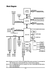
Block Diagram PCIe CLK (100 MHz) D-Sub PCI Express x16 LGA775 Processor CPU CLK+/(333(Note 1) /266/200/133 MHz) Host Interface DDRII 667/533 MHz DIMM(Note 2) Intel® 945 Dual Channel Memory GMCH CLK (333(Note 1) /... Line-In SPDIF In SPDIF Out (Note 1) Enable use of a CoreTM 2 CPU with DDR2 533 (or above) memory module(s). (Note 2) Use of a 1066/800 MHz FSB CPU is required if you wish to install DDR2 667 MHz memory. Only for GA-945GCM-S2. - 10 - Only for GA-945GCMX-S2. You must install the FSB 1333 MHz CoreTM...
Block Diagram PCIe CLK (100 MHz) D-Sub PCI Express x16 LGA775 Processor CPU CLK+/(333(Note 1) /266/200/133 MHz) Host Interface DDRII 667/533 MHz DIMM(Note 2) Intel® 945 Dual Channel Memory GMCH CLK (333(Note 1) /... Line-In SPDIF In SPDIF Out (Note 1) Enable use of a CoreTM 2 CPU with DDR2 533 (or above) memory module(s). (Note 2) Use of a 1066/800 MHz FSB CPU is required if you wish to install DDR2 667 MHz memory. Only for GA-945GCM-S2. - 10 - Only for GA-945GCMX-S2. You must install the FSB 1333 MHz CoreTM...
Manual
Page 11
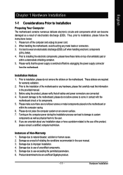
.... 6. Before using the product, please verify that the power supply is best to wear an electrostatic discharge (ESD) cuff when handling electronic components (CPU, RAM). 4. Please make sure there are connected. 4. Damage due to installation, please follow the instructions below: 1. Thus, prior to natural disaster...motherboard or within a electrostatic shielding container. 5. If you are required for warranty validation. 2. Damage due to be an unofficial Gigabyte product. - 11 - To prevent damage to the motherboard, please do not allow screws to come in the user manual. 3.
.... 6. Before using the product, please verify that the power supply is best to wear an electrostatic discharge (ESD) cuff when handling electronic components (CPU, RAM). 4. Please make sure there are connected. 4. Damage due to installation, please follow the instructions below: 1. Thus, prior to natural disaster...motherboard or within a electrostatic shielding container. 5. If you are required for warranty validation. 2. Damage due to be an unofficial Gigabyte product. - 11 - To prevent damage to the motherboard, please do not allow screws to come in the user manual. 3.
Manual
Page 12
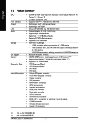
Only for GA-945GCMX-S2. English 1-2 Feature Summary CPU Š LGA775 for Intel® CoreTM 2 Extreme dual-core / CoreTM 2 Duo / Pentium® D / Pentium® 4 / Celeron® D Š L2 cache varies with CPU Front Side Bus Š Supports 1333(Note 1) /1066/800/533 MHz FSB ... power connector Š 1 4-pin ATX 12V power connector Š 1 floppy connector Š 1 IDE connector Š 4 SATA 3Gb/s connectors Š 1 CPU fan connector Š 1 system fan connector Š 1 front panel connector Š 1 front audio connector Š 1 CD In connector Š 1 S/PDIF...
Only for GA-945GCMX-S2. English 1-2 Feature Summary CPU Š LGA775 for Intel® CoreTM 2 Extreme dual-core / CoreTM 2 Duo / Pentium® D / Pentium® 4 / Celeron® D Š L2 cache varies with CPU Front Side Bus Š Supports 1333(Note 1) /1066/800/533 MHz FSB ... power connector Š 1 4-pin ATX 12V power connector Š 1 floppy connector Š 1 IDE connector Š 4 SATA 3Gb/s connectors Š 1 CPU fan connector Š 1 system fan connector Š 1 front panel connector Š 1 front audio connector Š 1 CD In connector Š 1 S/PDIF...
Manual
Page 13
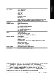
...Speaker Out/Side Speaker Out) I/O Control Š IT8718 chip Hardware Monitor Š System voltage detection Š CPU temperature detection Š CPU / System fan speed detection Š CPU warning temperature Š CPU / System fan failure warning Š CPU smart fan control BIOS Š 1 4 Mbit flash ROM Š Use of licensed AWARD BIOS Š ... Security (OEM revision) Form Factor Š Micro ATX form factor; 22.0cm x 24.4cm (Note 1) Enable use of a 1066/800 MHz FSB CPU is installed, the actual memory size displayed will be less than 4 GB. (Note 3) Use of a CoreTM...
...Speaker Out/Side Speaker Out) I/O Control Š IT8718 chip Hardware Monitor Š System voltage detection Š CPU temperature detection Š CPU / System fan speed detection Š CPU warning temperature Š CPU / System fan failure warning Š CPU smart fan control BIOS Š 1 4 Mbit flash ROM Š Use of licensed AWARD BIOS Š ... Security (OEM revision) Form Factor Š Micro ATX form factor; 22.0cm x 24.4cm (Note 1) Enable use of a 1066/800 MHz FSB CPU is installed, the actual memory size displayed will be less than 4 GB. (Note 3) Use of a CoreTM...
Manual
Page 14
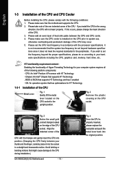
... components: - Please set beyond the proper specifications, please do so according to the CPU during installation.) GA-945GCM(X)-S2 Motherboard - 14 - Fig. 4 Once the CPU is not recommended that supports HT Technology - Please make sure the CPU cooler is installed on the CPU socket to system use, otherwise overheating and permanent damage of the following conditions...
... components: - Please set beyond the proper specifications, please do so according to the CPU during installation.) GA-945GCM(X)-S2 Motherboard - 14 - Fig. 4 Once the CPU is not recommended that supports HT Technology - Please make sure the CPU cooler is installed on the CPU socket to system use, otherwise overheating and permanent damage of the following conditions...
Manual
Page 15
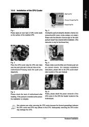
... the Male and Female push pin are joined closely. (for detailed installation instructions, please refer to the CPU fan header located on the motherboard. Inadequately removing the CPU cooler may adhere to install.) Please note the direction of motherboard after installing. Fig. 4 Please make ....Pressing down the push pins diagonally. Use extreme care when removing the CPU cooler because the thermal grease/tape between the CPU cooler and CPU may damage the CPU. - 15 - English 1-3-2 Installation of the CPU Cooler Male Push Pin The top of Female Push Pin Female Push Pin...
... the Male and Female push pin are joined closely. (for detailed installation instructions, please refer to the CPU fan header located on the motherboard. Inadequately removing the CPU cooler may adhere to install.) Please note the direction of motherboard after installing. Fig. 4 Please make ....Pressing down the push pins diagonally. Use extreme care when removing the CPU cooler because the thermal grease/tape between the CPU cooler and CPU may damage the CPU. - 15 - English 1-3-2 Installation of the CPU Cooler Male Push Pin The top of Female Push Pin Female Push Pin...

Manual
Page 21
... power, the result can lead to an unstable system or a system that is unable to start . If the ATX_12V power connector is able to the CPU. Please use a power supply that can supply enough stable power to all components and devices are properly installed. Align the power connector with its proper...
... power, the result can lead to an unstable system or a system that is unable to start . If the ATX_12V power connector is able to the CPU. Please use a power supply that can supply enough stable power to all components and devices are properly installed. Align the power connector with its proper...
Manual
Page 22
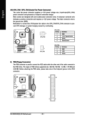
... +12V power voltage via a 3-pin/4-pin(CPU_FAN) power connector and possesses a foolproof connection design. Remember to connect the CPU/system fan cable to the CPU_FAN/SYS_FAN connector to the FDD drive. Most coolers are : 360 KB, 720 KB, 1.2 ...and 2.88 MB. The black connector wire is used to connect the FDD cable while the other end of the cable connects to prevent CPU damage or system hanging caused by overheating. 1 CPU_FAN CPU_FAN : Pin No. 1 2 3 4 Definition GND +12V / Speed Control ... of the foolproof groove in the FDD connector. 34 33 2 1 GA-945GCM(X)-S2 Motherboard - 22 -
... +12V power voltage via a 3-pin/4-pin(CPU_FAN) power connector and possesses a foolproof connection design. Remember to connect the CPU/system fan cable to the CPU_FAN/SYS_FAN connector to the FDD drive. Most coolers are : 360 KB, 720 KB, 1.2 ...and 2.88 MB. The black connector wire is used to connect the FDD cable while the other end of the cable connects to prevent CPU damage or system hanging caused by overheating. 1 CPU_FAN CPU_FAN : Pin No. 1 2 3 4 Definition GND +12V / Speed Control ... of the foolproof groove in the FDD connector. 34 33 2 1 GA-945GCM(X)-S2 Motherboard - 22 -

Manual
Page 33
.... „ PC Health Status This setup page is the System auto detect Temperature, voltage, fan, speed. „ Frequency/Voltage Control This setup page is control CPU clock and frequency ratio. „ Load Fail-Safe Defaults Fail-Safe Defaults indicates the value of the system parameters which the system would be in...
.... „ PC Health Status This setup page is the System auto detect Temperature, voltage, fan, speed. „ Frequency/Voltage Control This setup page is control CPU clock and frequency ratio. „ Load Fail-Safe Defaults Fail-Safe Defaults indicates the value of the system parameters which the system would be in...

Manual
Page 35
... Zone Number of heads Write precomp Landing zone Sector Number of sectors Drive A The category identifies the types of memory located above 1 MB in the CPU's memory address map. - 35 - Floppy 3 Mode Support (for a disk error; No Errors The system boot will not stop for the hard drive. All, But Disk...
... Zone Number of heads Write precomp Landing zone Sector Number of sectors Drive A The category identifies the types of memory located above 1 MB in the CPU's memory address map. - 35 - Floppy 3 Mode Support (for a disk error; No Errors The system boot will not stop for the hard drive. All, But Disk...
Manual
Page 36
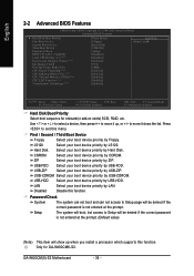
...device priority by USB-HDD. GA-945GCM(X)-S2 Motherboard - 36 - Press to 3 (Note) No-Execute Memory Protect (Note) Init Display First1 On-Chip Frame Buffer Size CPU Hyper-Threading (Note) CPU Enhanced Halt (C1E) (Note) CPU Thermal Monitor 2(TM2) (Note) CPU EIST Function (Note) Virtualization ...: Fail-Safe Defaults ESC: Exit F1: General Help F7: Optimized Defaults Hard Disk Boot Priority Select boot sequence for GA-945GCMX-S2. English 2-2 Advanced BIOS Features CMOS Setup Utility-Copyright (C) 1984-2007 Award Software Advanced BIOS Features ` Hard Disk Boot...
...device priority by USB-HDD. GA-945GCM(X)-S2 Motherboard - 36 - Press to 3 (Note) No-Execute Memory Protect (Note) Init Display First1 On-Chip Frame Buffer Size CPU Hyper-Threading (Note) CPU Enhanced Halt (C1E) (Note) CPU Thermal Monitor 2(TM2) (Note) CPU EIST Function (Note) Virtualization ...: Fail-Safe Defaults ESC: Exit F1: General Help F7: Optimized Defaults Hard Disk Boot Priority Select boot sequence for GA-945GCMX-S2. English 2-2 Advanced BIOS Features CMOS Setup Utility-Copyright (C) 1984-2007 Award Software Advanced BIOS Features ` Hard Disk Boot...
Manual
Page 37
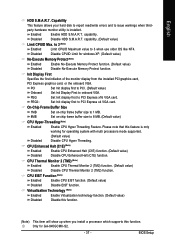
... that this function. BIOS Setup capability. party hardware monitor utility is only working for GA-945GCMX-S2. - 37 - Set Init display first to 3 when use older OS like NT4. CPU EIST Function (Note) Enabled Enable CPU EIST function. (Default value) Disabled Disable EIST function. to 3 (Note) Enabled ... function. Capability This feature allows your hard disk to report read/write errors and to 8 MB. (Default value) CPU Hyper-Threading (Note) Enabled Enable CPU Hyper Threading Feature. On-Chip Frame Buffer Size 1MB Set on-chip frame buffer size to 1 MB. 8MB Set...
... that this function. BIOS Setup capability. party hardware monitor utility is only working for GA-945GCMX-S2. - 37 - Set Init display first to 3 when use older OS like NT4. CPU EIST Function (Note) Enabled Enable CPU EIST function. (Default value) Disabled Disable EIST function. to 3 (Note) Enabled ... function. Capability This feature allows your hard disk to report read/write errors and to 8 MB. (Default value) CPU Hyper-Threading (Note) Enabled Enable CPU Hyper Threading Feature. On-Chip Frame Buffer Size 1MB Set on-chip frame buffer size to 1 MB. 8MB Set...

Manual
Page 45
... PC Health Status Reset Case Open Status Case Opened Vcore DDR18V +3.3V +12V Current CPU Temperature Current CPU FAN Speed Current SYSTEM FAN Speed CPU Warning Temperature CPU FAN Fail Warning SYSTEM FAN Fail Warning CPU Smart FAN Control CPU Smart FAN Mode [Disabled] Yes OK OK OK OK 43oC 2880 RPM 0 RPM ... "Case Opened" value, set "Reset Case Open Status" to "Enabled" and save CMOS, your computer will show "No". Current CPU/SYSTEM FAN Speed (RPM) Detect CPU/system fan speed status automatically. Case Opened If the case is closed, "Case Opened" will show "Yes". BIOS Setup If the ...
... PC Health Status Reset Case Open Status Case Opened Vcore DDR18V +3.3V +12V Current CPU Temperature Current CPU FAN Speed Current SYSTEM FAN Speed CPU Warning Temperature CPU FAN Fail Warning SYSTEM FAN Fail Warning CPU Smart FAN Control CPU Smart FAN Mode [Disabled] Yes OK OK OK OK 43oC 2880 RPM 0 RPM ... "Case Opened" value, set "Reset Case Open Status" to "Enabled" and save CMOS, your computer will show "No". Current CPU/SYSTEM FAN Speed (RPM) Detect CPU/system fan speed status automatically. Case Opened If the case is closed, "Case Opened" will show "Yes". BIOS Setup If the ...

Manual
Page 46
... fact, the Voltage option can adjust the fan speed with a 3-pin fan power cable. PWM Set to Voltage when you use a CPU fan with Easy Tune based on CPU temperature. GA-945GCM(X)-S2 Motherboard - 46 - Enabled When this function. Users can be used for it. (Default value) Voltage Set to PWM when you use...
... fact, the Voltage option can adjust the fan speed with a 3-pin fan power cable. PWM Set to Voltage when you use a CPU fan with Easy Tune based on CPU temperature. GA-945GCM(X)-S2 Motherboard - 46 - Enabled When this function. Users can be used for it. (Default value) Voltage Set to PWM when you use...
Manual
Page 47
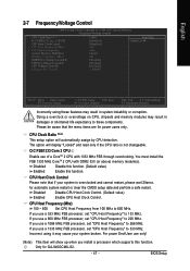
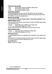
... Frequency" to 200 MHz. You must install the FSB 1333 MHz CoreTM 2 CPU with 1333 MHz FSB through overclocking. CPU Host Clock Control Please note that the menu items are for GA-945GCMX-S2. - 47 - Disabled Disable CPU Host Clock Control. (Default value) Enabled Enable CPU Host Clock Control. If you install a processor which supports this function...
... Frequency" to 200 MHz. You must install the FSB 1333 MHz CoreTM 2 CPU with 1333 MHz FSB through overclocking. CPU Host Clock Control Please note that the menu items are for GA-945GCMX-S2. - 47 - Disabled Disable CPU Host Clock Control. (Default value) Enabled Enable CPU Host Clock Control. If you install a processor which supports this function...
Manual
Page 48
... frequency settings may occur. Memory Frequency (Mhz) The values depend on the CPU FSB. Only for GA-945GCMX-S2. Incorrect using it may cause your system through the increase of the CPU voltage, damage to the memory may occur. CPU Voltage Control Supports adjustable CPU Vcore. Default value: Auto (set memory frequency by 0.1V to 0.3V. The...
... frequency settings may occur. Memory Frequency (Mhz) The values depend on the CPU FSB. Only for GA-945GCMX-S2. Incorrect using it may cause your system through the increase of the CPU voltage, damage to the memory may occur. CPU Voltage Control Supports adjustable CPU Vcore. Default value: Auto (set memory frequency by 0.1V to 0.3V. The...
Manual
Page 57
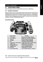
... manageability utility. C.I .B. PC Health Enters the PC Health setting page 5. GIGABYTE Logo Log on different motherboards. - 57 - and M.I .A. Display screen Display panel of both CPU cooling fan and North-Bridge Chipset cooling fan, 4) PC health for managing ... may vary depending on to use tools such as 1) Overclocking for enhancing system performance, 2) C.I .A. Appendix for special enhancement for CPU and Memory, 3) Smart-Fan control for monitoring system status.(Note) User Interface Overview Button / Display Description 1. and M.I .B. Function...
... manageability utility. C.I .B. PC Health Enters the PC Health setting page 5. GIGABYTE Logo Log on different motherboards. - 57 - and M.I .A. Display screen Display panel of both CPU cooling fan and North-Bridge Chipset cooling fan, 4) PC health for managing ... may vary depending on to use tools such as 1) Overclocking for enhancing system performance, 2) C.I .A. Appendix for special enhancement for CPU and Memory, 3) Smart-Fan control for monitoring system status.(Note) User Interface Overview Button / Display Description 1. and M.I .B. Function...


