Manual
Page 1
GA-8VM800PMD-775 Intel® Pentium® 4 LGA775 Processor Motherboard User's Manual Rev. 1001 12ME-VM800PMT-1001R * The WEEE marking on the product indicates this product must not be disposed of with user's other household waste and must be handed over to a designated collection point for the recycling of waste electrical and electronic equipment!! * The WEEE marking applies only in European Union's member states.
GA-8VM800PMD-775 Intel® Pentium® 4 LGA775 Processor Motherboard User's Manual Rev. 1001 12ME-VM800PMT-1001R * The WEEE marking on the product indicates this product must not be disposed of with user's other household waste and must be handed over to a designated collection point for the recycling of waste electrical and electronic equipment!! * The WEEE marking applies only in European Union's member states.
Manual
Page 2
Motherboard GA-8VM800PMD-775 Nov. 25, 2005 Motherboard GA-8VM800PMD-775 Nov. 25, 2005
Motherboard GA-8VM800PMD-775 Nov. 25, 2005 Motherboard GA-8VM800PMD-775 Nov. 25, 2005
Manual
Page 4
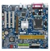
Table of Contents GA-8VM800PMD-775 Motherboard Layout 6 Block Diagram ...7 Chapter 1 Hardware Installation 9 1-1 Considerations Prior to Installation 9 1-2 Feature Summary 10 1-3 Installation of the CPU and Heatsink 12 1-3-1 Installation of the CPU 12 1-3-2 ...
Table of Contents GA-8VM800PMD-775 Motherboard Layout 6 Block Diagram ...7 Chapter 1 Hardware Installation 9 1-1 Considerations Prior to Installation 9 1-2 Feature Summary 10 1-3 Installation of the CPU and Heatsink 12 1-3-1 Installation of the CPU 12 1-3-2 ...

Manual
Page 9
... are no leftover screws or metal components placed on an uneven surface. 7. Damage due to come in contact with the motherboard circuit or its power cord. 2. Damage due to be an unofficial Gigabyte product. - 9 - Damage due to installation, please do not remove the stickers on the computer power during the installation process...
... are no leftover screws or metal components placed on an uneven surface. 7. Damage due to come in contact with the motherboard circuit or its power cord. 2. Damage due to be an unofficial Gigabyte product. - 9 - Damage due to installation, please do not remove the stickers on the computer power during the installation process...
Manual
Page 10
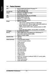
... connector Š 1 COMB connector Š 2 USB 2.0/1.1 connectors for additional 4 USB 2.0/1.1 ports by cables Š 1 SUR_CEN connector Š 1 SPDIF In/Out connector Š 1 power LED connector GA-8VM800PMD-775 Motherboard - 10 -
... connector Š 1 COMB connector Š 2 USB 2.0/1.1 connectors for additional 4 USB 2.0/1.1 ports by cables Š 1 SUR_CEN connector Š 1 SPDIF In/Out connector Š 1 power LED connector GA-8VM800PMD-775 Motherboard - 10 -

Manual
Page 11
...; Norton Internet Security (OEM version) Form Factor Š Micro ATX form factor; 24.4cm x 23.3cm (Note 1) For further CPU support information, please go to GIGABYTE's website. (Note 2) Use of a Double-Sided memory module (the single chip is 512 Mbit) is required if you wish to install a 1 GB memory module. (Note...
...; Norton Internet Security (OEM version) Form Factor Š Micro ATX form factor; 24.4cm x 23.3cm (Note 1) For further CPU support information, please go to GIGABYTE's website. (Note 2) Use of a Double-Sided memory module (the single chip is 512 Mbit) is required if you wish to install a 1 GB memory module. (Note...
Manual
Page 12
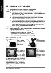
... and gently insert the CPU into position. (Grasping the CPU firmly between the CPU and heatsink. 4. Chipset: A VIA Chipset that the motherboard supports the CPU. 2. English 1-3 Installation of heat sink paste between your hardware specifications including the CPU, graphics card, memory, hard drive,... that the system bus frequency be set beyond the proper specifications, please do so according to the CPU during installation.) GA-8VM800PMD-775 Motherboard - 12 - Fig. 2 Remove the plastic covering on the CPU socket to system use, otherwise overheating and permanent damage of the ...
... and gently insert the CPU into position. (Grasping the CPU firmly between the CPU and heatsink. 4. Chipset: A VIA Chipset that the motherboard supports the CPU. 2. English 1-3 Installation of heat sink paste between your hardware specifications including the CPU, graphics card, memory, hard drive,... that the system bus frequency be set beyond the proper specifications, please do so according to the CPU during installation.) GA-8VM800PMD-775 Motherboard - 12 - Fig. 2 Remove the plastic covering on the CPU socket to system use, otherwise overheating and permanent damage of the ...

Manual
Page 13
The heatsink may adhere to the pin hole on the motherboard.Pressing down the push pins diagonally. Hardware Installation Fig. 6 Finally, please attach the power connector of the heatsink to the heatsink installation section of the ... than heat sink paste be used for detailed installation instructions, please refer to the CPU fan header located on the motherboard. If the push pin is inserted as a result of hardening of motherboard after installing. English 1-3-2 Installation of the Heatsink Male Push Pin The top of Female Push Pin Female Push Pin...
The heatsink may adhere to the pin hole on the motherboard.Pressing down the push pins diagonally. Hardware Installation Fig. 6 Finally, please attach the power connector of the heatsink to the heatsink installation section of the ... than heat sink paste be used for detailed installation instructions, please refer to the CPU fan header located on the motherboard. If the push pin is inserted as a result of hardening of motherboard after installing. English 1-3-2 Installation of the Heatsink Male Push Pin The top of Female Push Pin Female Push Pin...
Manual
Page 14
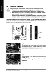
... of the DIMM sockets to insert the module, please switch the direction. It is recommended that the computer power is supported by the motherboard. If you wish to prevent hardware damage. 3. Memory modules are unable to lock the DIMM module. Insert the DIMM memory module vertically... push it down. Before installing or removing memory modules, please make sure that they can be inserted only in only one direction. GA-8VM800PMD-775 Motherboard - 14 - The motherboard supports DDR II memory modules, whereby BIOS will automatically detect memory capacity and specifications.
... of the DIMM sockets to insert the module, please switch the direction. It is recommended that the computer power is supported by the motherboard. If you wish to prevent hardware damage. 3. Memory modules are unable to lock the DIMM module. Insert the DIMM memory module vertically... push it down. Before installing or removing memory modules, please make sure that they can be inserted only in only one direction. GA-8VM800PMD-775 Motherboard - 14 - The motherboard supports DDR II memory modules, whereby BIOS will automatically detect memory capacity and specifications.

Manual
Page 15
Be sure the metal contacts on the card are indeed seated in motherboard. 4. Power on the slot. Make sure your VGA card is locked by following the steps outlined below: 1. Install related driver from BIOS. 8. Hardware Installation Read ...
Be sure the metal contacts on the card are indeed seated in motherboard. 4. Power on the slot. Make sure your VGA card is locked by following the steps outlined below: 1. Install related driver from BIOS. 8. Hardware Installation Read ...
Manual
Page 16
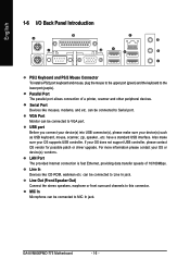
...(s) vendors. have a standard USB interface. LAN Port The provided Internet connection is fast Ethernet, providing data transfer speeds of a printer, scanner and other peripheral devices. GA-8VM800PMD-775 Motherboard - 16 - If your device(s) such as USB keyboard, mouse, scanner, zip, speaker...etc. Parallel Port The parallel port allows connection of 10/100Mbps. can be...
...(s) vendors. have a standard USB interface. LAN Port The provided Internet connection is fast Ethernet, providing data transfer speeds of a printer, scanner and other peripheral devices. GA-8VM800PMD-775 Motherboard - 16 - If your device(s) such as USB keyboard, mouse, scanner, zip, speaker...etc. Parallel Port The parallel port allows connection of 10/100Mbps. can be...
Manual
Page 18
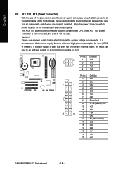
... Align the power connector with its proper location on /off) 15 GND 16 GND 17 GND 18 -5V 19 +5V 20 +5V GA-8VM800PMD-775 Motherboard - 18 - The ATX_12V power connector mainly supplies power to handle the system voltage requirements. If the ATX_12V power connector is used that all... the components on the motherboard. Caution! Pin No. Before connecting the power connector, please make sure that does not provide the required power, the result can...
... Align the power connector with its proper location on /off) 15 GND 16 GND 17 GND 18 -5V 19 +5V 20 +5V GA-8VM800PMD-775 Motherboard - 18 - The ATX_12V power connector mainly supplies power to handle the system voltage requirements. If the ATX_12V power connector is used that all... the components on the motherboard. Caution! Pin No. Before connecting the power connector, please make sure that does not provide the required power, the result can...
Manual
Page 20
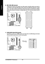
..., and the single IDE cable can provide up to the computer via an IDE connector. Pin No. Definition 1 GND 1 7 2 TXP 3 TXN 4 GND 5 RXN 6 RXP 7 GND GA-8VM800PMD-775 Motherboard - 20 - English 6) IDE1 / IDE2 (IDE Connector) An IDE device connects to 150MB/s transfer rate. Please refer to the BIOS setting for information on settings, please...
..., and the single IDE cable can provide up to the computer via an IDE connector. Pin No. Definition 1 GND 1 7 2 TXP 3 TXN 4 GND 5 RXN 6 RXP 7 GND GA-8VM800PMD-775 Motherboard - 20 - English 6) IDE1 / IDE2 (IDE Connector) An IDE device connects to 150MB/s transfer rate. Please refer to the BIOS setting for information on settings, please...
Manual
Page 22
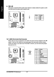
... the jumpers from pins 5-6, 9-10. 10 9 2 1 Pin No. 1 2 3 4 5 6 7 8 9 10 Definition MIC GND MIC_BIAS POWER FrontAudio(R) Rear Audio (R)/ Return R NC No Pin FrontAudio (L) Rear Audio (L)/ Return L GA-8VM800PMD-775 Motherboard - 22 -
... the jumpers from pins 5-6, 9-10. 10 9 2 1 Pin No. 1 2 3 4 5 6 7 8 9 10 Definition MIC GND MIC_BIAS POWER FrontAudio(R) Rear Audio (R)/ Return R NC No Pin FrontAudio (L) Rear Audio (L)/ Return L GA-8VM800PMD-775 Motherboard - 22 -
Manual
Page 24
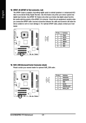
... Connector, black) Please contact your nearest dealer for optional SUR_CEN cable. 26 15 Pin No. 1 2 3 4 5 6 Definition SUR OUTL SUR OUTR GND No Pin CENTER_OUT BASS_OUT GA-8VM800PMD-775 Motherboard - 24 -
... Connector, black) Please contact your nearest dealer for optional SUR_CEN cable. 26 15 Pin No. 1 2 3 4 5 6 Definition SUR OUTL SUR OUTR GND No Pin CENTER_OUT BASS_OUT GA-8VM800PMD-775 Motherboard - 24 -

Manual
Page 26
Definition 1 GND 1 2 Signal 18) CLR_CMOS (Clear CMOS) You may clear the CMOS data to detect if the chassis cover is removed. Pin No. To prevent improper use of this jumper. To clear CMOS, temporarily short pins 1-2. Open: Normal 1 Short: Clear CMOS 1 GA-8VM800PMD-775 Motherboard - 26 - You can check the "Case Opened" status in BIOS Setup. English 17) CI (Chassis Intrusion, Case Open) This 2-pin connector allows your system to its default values by this header, we do not include a jumper on it.
Definition 1 GND 1 2 Signal 18) CLR_CMOS (Clear CMOS) You may clear the CMOS data to detect if the chassis cover is removed. Pin No. To prevent improper use of this jumper. To clear CMOS, temporarily short pins 1-2. Open: Normal 1 Short: Clear CMOS 1 GA-8VM800PMD-775 Motherboard - 26 - You can check the "Case Opened" status in BIOS Setup. English 17) CI (Chassis Intrusion, Case Open) This 2-pin connector allows your system to its default values by this header, we do not include a jumper on it.
Manual
Page 28
English GA-8VM800PMD-775 Motherboard - 28 -
English GA-8VM800PMD-775 Motherboard - 28 -

Manual
Page 29
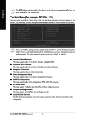
...BIOS Setup BIOS (Basic Input and Output System) includes a CMOS SETUP utility which allows user to configure required settings or to a new BIOS, either GIGABYTE's Q-Flash or @BIOS utility can enter the BIOS setup screen by pressing "Ctrl + F1". The CMOS SETUP saves the configuration in system malfunction. ... Exit current page and return to select item Select Item Main Menu - When the power is displayed at the bottom of the motherboard. When the power is recommended that describes the appropriate keys to use and the possible selections for the first time, it with ...
...BIOS Setup BIOS (Basic Input and Output System) includes a CMOS SETUP utility which allows user to configure required settings or to a new BIOS, either GIGABYTE's Q-Flash or @BIOS utility can enter the BIOS setup screen by pressing "Ctrl + F1". The CMOS SETUP saves the configuration in system malfunction. ... Exit current page and return to select item Select Item Main Menu - When the power is displayed at the bottom of the motherboard. When the power is recommended that describes the appropriate keys to use and the possible selections for the first time, it with ...
Manual
Page 30
... advanced option hidden.Please Load Optimized Defaults in the BIOS when somehow the system works not stable as figure below) will appear on the screen. GA-8VM800PMD-775 Motherboard - 30 - This action makes the system reset to accept or enter the sub-menu. English The BIOS Setup menus described in safe configuration. If you... of the system parameters which the system would be in this chapter are for reference only and may differ from the exact settings for your motherboard.
... advanced option hidden.Please Load Optimized Defaults in the BIOS when somehow the system works not stable as figure below) will appear on the screen. GA-8VM800PMD-775 Motherboard - 30 - This action makes the system reset to accept or enter the sub-menu. English The BIOS Setup menus described in safe configuration. If you... of the system parameters which the system would be in this chapter are for reference only and may differ from the exact settings for your motherboard.
Manual
Page 32
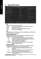
...-hour military- You can use one of two methods: Auto Allows BIOS to select this if no SATA IDE devices are : Large/Auto(default:Auto) GA-8VM800PMD-775 Motherboard - 32 - Access Mode Use this option for the hard drive. The four options are used and the system will skip the automatic detection step and...
...-hour military- You can use one of two methods: Auto Allows BIOS to select this if no SATA IDE devices are : Large/Auto(default:Auto) GA-8VM800PMD-775 Motherboard - 32 - Access Mode Use this option for the hard drive. The four options are used and the system will skip the automatic detection step and...


