Manual
Page 4
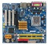
Table of Contents ItemChecklist ...6 OptionalAccessories ...6 GA-8I945GZME-RH Motherboard Layout 7 Block Diagram ...8 Chapter 1 Hardware Installation 9 1-1 Considerations Prior to Installation 9 1-2 Feature Summary 10 1-3 Installation of the CPU and CPU Cooler 12 1-3-1 Installation of the CPU 12 1-3-2 Installation of the Heatsink 13 1-4 Installation of Memory 14 1-5 Installation of Expansion Cards 15 1-5-1 Graphics Card Support List 16 1-6 I/O Back Panel Introduction...
Table of Contents ItemChecklist ...6 OptionalAccessories ...6 GA-8I945GZME-RH Motherboard Layout 7 Block Diagram ...8 Chapter 1 Hardware Installation 9 1-1 Considerations Prior to Installation 9 1-2 Feature Summary 10 1-3 Installation of the CPU and CPU Cooler 12 1-3-1 Installation of the CPU 12 1-3-2 Installation of the Heatsink 13 1-4 Installation of Memory 14 1-5 Installation of Expansion Cards 15 1-5-1 Graphics Card Support List 16 1-6 I/O Back Panel Introduction...
Manual
Page 9
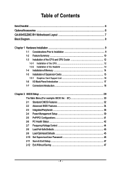
...metal leads or connectors. 3. Hardware Installation Before using the product, please verify that the power supply is best to be an unofficial Gigabyte product. - 9 - Prior to installation, please do not allow screws to come in the provided manual. 3. Damage due to ...do not remove the stickers on an uneven surface. 7. Product determined to wear an electrostatic discharge (ESD) cuff when handling electronic components (CPU, RAM). 4. It is switched off the computer and unplug its components. 5. Damage as a result of uncertified components. 5. Please ...
...metal leads or connectors. 3. Hardware Installation Before using the product, please verify that the power supply is best to be an unofficial Gigabyte product. - 9 - Prior to installation, please do not allow screws to come in the provided manual. 3. Damage due to ...do not remove the stickers on an uneven surface. 7. Product determined to wear an electrostatic discharge (ESD) cuff when handling electronic components (CPU, RAM). 4. It is switched off the computer and unplug its components. 5. Damage as a result of uncertified components. 5. Please ...
Manual
Page 10
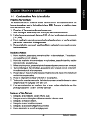
...; Supports LGA775 Intel® Pentium® 4 Processor (Note 1) Š L2 cache varies with CPU Front Side Bus Š Supports 800/533MHz FSB Chipset Northbridge: Intel® 945GZ Š Southbridge: Intel® ICH7...Š 1 CPU fan connector Š 1 system fan connector Š 1 front panel connector Š 1 front audio connector Š 1 CD In connector Š 1 COMB connector Š 1 power LED connector Š 2 USB 2.0/1.1 connectors for additional 4 USB 2.0/1.1 ports by cables Š 1 SPDIF In/Out connector Š 1 HDA_SUR connector GA-8I945GZME-RH Motherboard - 10...
...; Supports LGA775 Intel® Pentium® 4 Processor (Note 1) Š L2 cache varies with CPU Front Side Bus Š Supports 800/533MHz FSB Chipset Northbridge: Intel® 945GZ Š Southbridge: Intel® ICH7...Š 1 CPU fan connector Š 1 system fan connector Š 1 front panel connector Š 1 front audio connector Š 1 CD In connector Š 1 COMB connector Š 1 power LED connector Š 2 USB 2.0/1.1 connectors for additional 4 USB 2.0/1.1 ports by cables Š 1 SPDIF In/Out connector Š 1 HDA_SUR connector GA-8I945GZME-RH Motherboard - 10...
Manual
Page 11
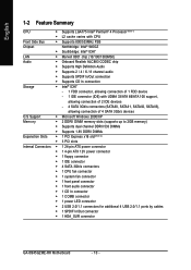
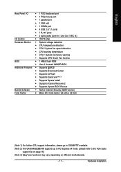
... I/O Control Š IT8718 chip Hardware Monitor Š System voltage detection Š CPU temperature detection Š CPU / System fan speed detection Š CPU warning temperature Š CPU / System fan failure warning Š Supports CPU Smart Fan function BIOS Š 1 4Mbit flash ROM Š Use of licensed ... version) Form Factor Š Micro ATX form factor; 24.4cm x 22.0cm (Note 1) For further CPU support information, please go to GIGABYTE's website. (Note 2) The GA-8I945GZME-RH supports up to PCI Express x4 mode. (please refer to the VGA cards support list on page 16)...
... I/O Control Š IT8718 chip Hardware Monitor Š System voltage detection Š CPU temperature detection Š CPU / System fan speed detection Š CPU warning temperature Š CPU / System fan failure warning Š Supports CPU Smart Fan function BIOS Š 1 4Mbit flash ROM Š Use of licensed ... version) Form Factor Š Micro ATX form factor; 24.4cm x 22.0cm (Note 1) For further CPU support information, please go to GIGABYTE's website. (Note 2) The GA-8I945GZME-RH supports up to PCI Express x4 mode. (please refer to the VGA cards support list on page 16)...
Manual
Page 12
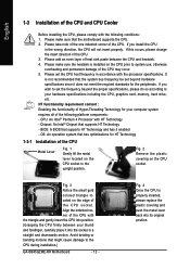
... the proper specifications, please do so according to the CPU during installation.) GA-8I945GZME-RH Motherboard - 12 - Please make sure that supports HT Technology and has it enabled - Fig. 2 Remove the plastic covering on the edge of the CPU socket. Fig. 4 Once the CPU is installed on the CPU socket to system use, otherwise overheating and permanent...
... the proper specifications, please do so according to the CPU during installation.) GA-8I945GZME-RH Motherboard - 12 - Please make sure that supports HT Technology and has it enabled - Fig. 2 Remove the plastic covering on the edge of the CPU socket. Fig. 4 Once the CPU is installed on the CPU socket to system use, otherwise overheating and permanent...
Manual
Page 13
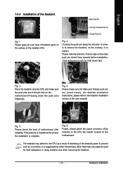
... the male push pin doesn't face inwards before installation. (This instruction is only for Intel boxed fan) Fig. 3 Place the heatsink atop the CPU and make sure the Male and Female push pin are joined closely. (for detailed installation instructions, please refer to the...used for heat dissipation or using extreme care when removing the heatsink. - 13 - Fig. 2 (Turning the push pin along the direction of the installed CPU. The heatsink may adhere to install.) Please note the direction of the heatsink paste.To prevent such an occurrence, it is complete. Hardware Installation If...
... the male push pin doesn't face inwards before installation. (This instruction is only for Intel boxed fan) Fig. 3 Place the heatsink atop the CPU and make sure the Male and Female push pin are joined closely. (for detailed installation instructions, please refer to the...used for heat dissipation or using extreme care when removing the heatsink. - 13 - Fig. 2 (Turning the push pin along the direction of the installed CPU. The heatsink may adhere to install.) Please note the direction of the heatsink paste.To prevent such an occurrence, it is complete. Hardware Installation If...
Manual
Page 15
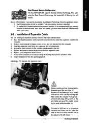
... white-drawable bar. To install a VGA card or to use memory modules of the expansion card. 6. English Dual Channel Memory Configuration The GA-8I945GZME-RH supports the Dual Channel Technology. To enable Dual Channel mode with two memory modules (it is locked by following the steps outlined below : ...1. Due to CPU limitation, if you wish to install/ uninstall the VGA card. Replace the screw to secure the slot bracket of identical brand, size, chips...
... white-drawable bar. To install a VGA card or to use memory modules of the expansion card. 6. English Dual Channel Memory Configuration The GA-8I945GZME-RH supports the Dual Channel Technology. To enable Dual Channel mode with two memory modules (it is locked by following the steps outlined below : ...1. Due to CPU limitation, if you wish to install/ uninstall the VGA card. Replace the screw to secure the slot bracket of identical brand, size, chips...
Manual
Page 19
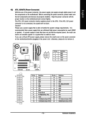
... that does not provide the required power, the result can lead to an unstable system or a system that can supply enough stable power to the CPU. English 1/2) ATX_12V/ATX (Power Connector) With the use of the power connector, the power supply can withstand high power consumption be used (300W or greater...
... that does not provide the required power, the result can lead to an unstable system or a system that can supply enough stable power to the CPU. English 1/2) ATX_12V/ATX (Power Connector) With the use of the power connector, the power supply can withstand high power consumption be used (300W or greater...
Manual
Page 20
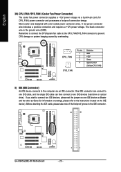
...is the ground wire (GND). Before attaching the IDE cable, please take note of the foolproof groove in the IDE connector. 40 39 GA-8I945GZME-RH Motherboard 2 1 - 20 - Most coolers are designed with color-coded power connector wires. One IDE connector can connect to one IDE...optical drive). A red power connector wire indicates a positive connection and requires a +12V power voltage. Remember to connect the CPU/system fan cable to the CPU_FAN/SYS_FAN connector to prevent CPU damage or system hanging caused by overheating. 1 CPU_FAN 1 SYS_FAN Pin No. 1 2 3 4 Definition GND +12V Sense...
...is the ground wire (GND). Before attaching the IDE cable, please take note of the foolproof groove in the IDE connector. 40 39 GA-8I945GZME-RH Motherboard 2 1 - 20 - Most coolers are designed with color-coded power connector wires. One IDE connector can connect to one IDE...optical drive). A red power connector wire indicates a positive connection and requires a +12V power voltage. Remember to connect the CPU/system fan cable to the CPU_FAN/SYS_FAN connector to prevent CPU damage or system hanging caused by overheating. 1 CPU_FAN 1 SYS_FAN Pin No. 1 2 3 4 Definition GND +12V Sense...

Manual
Page 31
.... „ PC Health Status This setup page is the System auto detect Temperature, voltage, fan, speed. „ Frequency/Voltage Control This setup page is control CPU clock and frequency ratio. „ Load Fail-Safe Defaults Fail-Safe Defaults indicates the value of the system parameters which the system would be in...
.... „ PC Health Status This setup page is the System auto detect Temperature, voltage, fan, speed. „ Frequency/Voltage Control This setup page is control CPU clock and frequency ratio. „ Load Fail-Safe Defaults Fail-Safe Defaults indicates the value of the system parameters which the system would be in...

Manual
Page 33
... value) Drive A Drive A is determined by POST (Power On Self Test) of currently installed hard drive. The value of memory located above 1 MB in the CPU's memory address map. - 33 - English Capacity Capacity of the BIOS. Memory The category is display-only which is 3 mode Floppy Drive. BIOS Setup All Errors...
... value) Drive A Drive A is determined by POST (Power On Self Test) of currently installed hard drive. The value of memory located above 1 MB in the CPU's memory address map. - 33 - English Capacity Capacity of the BIOS. Memory The category is display-only which is 3 mode Floppy Drive. BIOS Setup All Errors...
Manual
Page 34
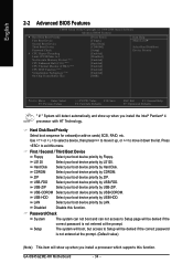
...exit this function. Hard Disk Select your boot device priority by Hard Disk. USB-ZIP Select your boot device priority by USB-ZIP. GA-8I945GZME-RH Motherboard - 34 - USB-HDD Select your boot device priority by USB-HDD. Setup The system will boot, but access to 3 No...-Execute Memory Protect (Note) CPU Enhanced Halt (C1E) (Note) CPU Thermal Monitor 2(TM2) (Note) CPU EIST Function (Note) Virtualization Technology (Note) On-Chip Frame Buffer Size [Press Enter] [Floppy] [Hard Disk] [CDROM] ...
...exit this function. Hard Disk Select your boot device priority by Hard Disk. USB-ZIP Select your boot device priority by USB-ZIP. GA-8I945GZME-RH Motherboard - 34 - USB-HDD Select your boot device priority by USB-HDD. Setup The system will boot, but access to 3 No...-Execute Memory Protect (Note) CPU Enhanced Halt (C1E) (Note) CPU Thermal Monitor 2(TM2) (Note) CPU EIST Function (Note) Virtualization Technology (Note) On-Chip Frame Buffer Size [Press Enter] [Floppy] [Hard Disk] [CDROM] ...

Manual
Page 35
...Disabled Disables CPUID Limit for operating system with multi processors mode supported. CPU Thermal Monitor 2 (TM2) (Note) Enabled Disabled Enable CPU Thermal Monitor 2 (TM2) function. (Default value) Disable CPU Thermal Monitor 2 (TM2) function. to 3 Enabled Limit CPUID Maximum... frame buffer size to 3 when use older OS like NT4. English CPU Hyper-Threading Enabled Enables CPU Hyper Threading Feature. BIOS Setup Disabled (Default value) Disables CPU Hyper Threading. Virtualization Technology (Note) Enabled Disabled Enable Virtualization technology function....
...Disabled Disables CPUID Limit for operating system with multi processors mode supported. CPU Thermal Monitor 2 (TM2) (Note) Enabled Disabled Enable CPU Thermal Monitor 2 (TM2) function. (Default value) Disable CPU Thermal Monitor 2 (TM2) function. to 3 Enabled Limit CPUID Maximum... frame buffer size to 3 when use older OS like NT4. English CPU Hyper-Threading Enabled Enables CPU Hyper Threading Feature. BIOS Setup Disabled (Default value) Disables CPU Hyper Threading. Virtualization Technology (Note) Enabled Disabled Enable Virtualization technology function....

Manual
Page 42
... restart. GA-8I945GZME-RH Motherboard - 42 - Current CPU Temperature Detect CPU temperature automatically. Disable this function. (Default value) CPU/System FAN Fail Warning Disabled Enabled Disable fan warning function. (Default value) Enable fan warning function. Current CPU/SYSTEM FAN Speed (RPM) Detect CPU/System fan...Open Status Case Opened Vcore DDR18V +3.3V +12V Current CPU Temperature Current CPU FAN Speed Current SYSTEM FAN Speed CPU Warning Temperature CPU FAN Fail Warning SYSTEM FAN Fail Warning CPU Smart FAN Control CPU Smart FAN Mode [Disabled] Yes OK OK OK OK...
... restart. GA-8I945GZME-RH Motherboard - 42 - Current CPU Temperature Detect CPU temperature automatically. Disable this function. (Default value) CPU/System FAN Fail Warning Disabled Enabled Disable fan warning function. (Default value) Enable fan warning function. Current CPU/SYSTEM FAN Speed (RPM) Detect CPU/System fan...Open Status Case Opened Vcore DDR18V +3.3V +12V Current CPU Temperature Current CPU FAN Speed Current SYSTEM FAN Speed CPU Warning Temperature CPU FAN Fail Warning SYSTEM FAN Fail Warning CPU Smart FAN Control CPU Smart FAN Mode [Disabled] Yes OK OK OK OK...

Manual
Page 43
...run at different speed depending on their requirements. (Default value) CPU Smart FAN Mode This option is available only when CPU Smart FAN Control is enabled, CPU fan will not effectively reduce the fan speed. - 43 - English CPU Smart FAN Control Disabled Disable this function is enabled. Users can ...be used for it. (Default Value) Voltage Set to PWM when you use a CPU fan with Easy Tune based on CPU temperature. PWM Set to Voltage when you use a CPU fan with 3-pin or 4-pin power cables. Enabled When this function. However, some 4-pin...
...run at different speed depending on their requirements. (Default value) CPU Smart FAN Mode This option is available only when CPU Smart FAN Control is enabled, CPU fan will not effectively reduce the fan speed. - 43 - English CPU Smart FAN Control Disabled Disable this function is enabled. Users can ...be used for it. (Default Value) Voltage Set to PWM when you use a CPU fan with Easy Tune based on CPU temperature. PWM Set to Voltage when you use a CPU fan with 3-pin or 4-pin power cables. Enabled When this function. However, some 4-pin...

Manual
Page 44
... (Mhz) The values depend on "System Memory Multiplier" item. (Note) This item will display "Locked" and read only if the CPU ratio is unclocked KLJI: Move Enter: Select F5: Previous Values +/-/PU/PD: Value F10: Save F6: Fail-Safe Defaults ESC: Exit... The option will show up when you install a processor which supports this function. GA-8I945GZME-RH Motherboard - 44 - System Memory Multiplier Wrong frequency may cause your system broken. Auto Set Memory frequency by CPU detection. English 2-7 Frequency/Voltage Control CMOS Setup Utility-Copyright (C) 1984-2006 Award ...
... (Mhz) The values depend on "System Memory Multiplier" item. (Note) This item will display "Locked" and read only if the CPU ratio is unclocked KLJI: Move Enter: Select F5: Previous Values +/-/PU/PD: Value F10: Save F6: Fail-Safe Defaults ESC: Exit... The option will show up when you install a processor which supports this function. GA-8I945GZME-RH Motherboard - 44 - System Memory Multiplier Wrong frequency may cause your system broken. Auto Set Memory frequency by CPU detection. English 2-7 Frequency/Voltage Control CMOS Setup Utility-Copyright (C) 1984-2006 Award ...

Manual
Page 53
... 8. Overclocking Enters the Overclocking setting page 2. GO Confirmation and Execution button 6. GIGABYTE Logo Log on different motherboards. - 53 - Featuring several powerful yet easy to GIGABYTE website 10. C.I.A./C.I.A.2 and M.I .B. Display screen Display panel of both CPU cooling fan and North-Bridge Chipset cooling fan, 4) PC health for enhancing system performance, 2) C.I .B. and M.I .B. setting page 3. Help...
... 8. Overclocking Enters the Overclocking setting page 2. GO Confirmation and Execution button 6. GIGABYTE Logo Log on different motherboards. - 53 - Featuring several powerful yet easy to GIGABYTE website 10. C.I.A./C.I.A.2 and M.I .B. Display screen Display panel of both CPU cooling fan and North-Bridge Chipset cooling fan, 4) PC health for enhancing system performance, 2) C.I .B. and M.I .B. setting page 3. Help...


