Manual
Page 1
GA-8I915G-MF GA-8I915GM Intel® Pentium® 4 LGA775 Processor Motherboard User's Manual Rev. 2204 12ME-8I915GMF-2204 * The WEEE marking on the product indicates this product must not be disposed of with user's other household waste and must be handed over to a designated collection point for the recycling of waste electrical and electronic equipment!! * The WEEE marking applies only in European Union's member states.
GA-8I915G-MF GA-8I915GM Intel® Pentium® 4 LGA775 Processor Motherboard User's Manual Rev. 2204 12ME-8I915GMF-2204 * The WEEE marking on the product indicates this product must not be disposed of with user's other household waste and must be handed over to a designated collection point for the recycling of waste electrical and electronic equipment!! * The WEEE marking applies only in European Union's member states.
Manual
Page 2
Motherboard GA-8I915G-MF Jun. 11, 2004 Motherboard GA-8I915G-MF Jun. 11, 2004
Motherboard GA-8I915G-MF Jun. 11, 2004 Motherboard GA-8I915G-MF Jun. 11, 2004
Manual
Page 4
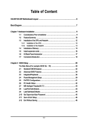
Table of Content GA-8I915G-MF Motherboard Layout 6 Block Diagram ...7 Chapter 1 Hardware Installation 9 1-1 Considerations Prior to Installation 9 1-2 Feature Summary 10 1-3 Installation of the CPU and Heatsink 12 1-3-1 Installation of the CPU 12 1-3-2 ...
Table of Content GA-8I915G-MF Motherboard Layout 6 Block Diagram ...7 Chapter 1 Hardware Installation 9 1-1 Considerations Prior to Installation 9 1-2 Feature Summary 10 1-3 Installation of the CPU and Heatsink 12 1-3-1 Installation of the CPU 12 1-3-2 ...
Manual
Page 6
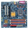
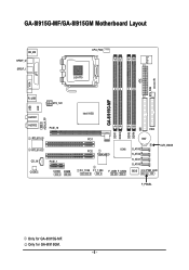
GA-8I915G-MF/GA-8I915GM Motherboard Layout IT8712 KB_MS SPDIF_O SPDIF_I CPU_FAN LGA775 SYS_FAN IR ATX VGA LPT R_USB ATX_12V USB LAN AZALIA_FP AUDIO1 AUDIO2 PCIE_16 RTL8110S RTL8100C CD_IN CODEC PCIE_1 COMA COMB GA-8I915G-MF DDR1 DDR2 Intel 915G IDE FDD DDR3 DDR4 PCI1 PCI2 ICH6 TSB43AB23 F2_1394 F1_1394 F_USB1 F_USB2 BAT S_ATA3 S_ATA2 S_ATA1 S_ATA0 CLR_CMOS BIOS PWR_LED F_PANEL Only for GA-8I915GM. - 6 - Only for GA-8I915G-MF.
GA-8I915G-MF/GA-8I915GM Motherboard Layout IT8712 KB_MS SPDIF_O SPDIF_I CPU_FAN LGA775 SYS_FAN IR ATX VGA LPT R_USB ATX_12V USB LAN AZALIA_FP AUDIO1 AUDIO2 PCIE_16 RTL8110S RTL8100C CD_IN CODEC PCIE_1 COMA COMB GA-8I915G-MF DDR1 DDR2 Intel 915G IDE FDD DDR3 DDR4 PCI1 PCI2 ICH6 TSB43AB23 F2_1394 F1_1394 F_USB1 F_USB2 BAT S_ATA3 S_ATA2 S_ATA1 S_ATA0 CLR_CMOS BIOS PWR_LED F_PANEL Only for GA-8I915GM. - 6 - Only for GA-8I915G-MF.

Manual
Page 9
...installation. 4. Hardware Installation Installation Notices 1. English Chapter 1 Hardware Installation 1-1 Considerations Prior to Installation Preparing Your Computer The motherboard contains numerous delicate electronic circuits and components which can lead to damage to system components as well as a result of ..., please first carefully read the information in contact with the motherboard circuit or its power cord. 2. Instances of the motherboard or any metal leads or connectors. 3. Prior to be an unofficial Gigabyte product. - 9 - Damage as a result of an antistatic...
...installation. 4. Hardware Installation Installation Notices 1. English Chapter 1 Hardware Installation 1-1 Considerations Prior to Installation Preparing Your Computer The motherboard contains numerous delicate electronic circuits and components which can lead to damage to system components as well as a result of ..., please first carefully read the information in contact with the motherboard circuit or its power cord. 2. Instances of the motherboard or any metal leads or connectors. 3. Prior to be an unofficial Gigabyte product. - 9 - Damage as a result of an antistatic...
Manual
Page 10
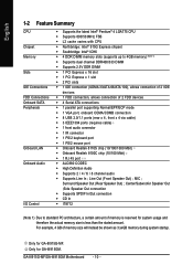
... Speaker Out) ; Surround Speaker Out (Rear Speaker Out) ; For example, 4 GB of memory size will instead be shown as 3.xxGB memory during system startup. GA-8I915G-MF/GA-8I915GM Motherboard - 10 - English 1-2 Feature Summary CPU Chipset Memory Slots IDE Connections FDD Connections Onboard SATA Peripherals Onboard LAN Onboard Audio I/O Control Š Supports the latest...
... Speaker Out) ; Surround Speaker Out (Rear Speaker Out) ; For example, 4 GB of memory size will instead be shown as 3.xxGB memory during system startup. GA-8I915G-MF/GA-8I915GM Motherboard - 10 - English 1-2 Feature Summary CPU Chipset Memory Slots IDE Connections FDD Connections Onboard SATA Peripherals Onboard LAN Onboard Audio I/O Control Š Supports the latest...
Manual
Page 12
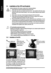
... Installation of the CPU Metal Lever Fig. 1 Gently lift the metal lever located on the CPU prior to the CPU during installation.) GA-8I915G-MF/GA-8I915GM Motherboard - 12 - Chipset: An Intel® Chipset that supports HT Technology and has it into its original position. Please add an even ...back into the socket in the wrong direction, the CPU will not insert properly. Fig. 4 Once the CPU is not recommended that the motherboard supports the CPU. 2. English 1-3 Installation of the CPU and Heatsink Before installing the CPU, please comply with HT Technology - Please make ...
... Installation of the CPU Metal Lever Fig. 1 Gently lift the metal lever located on the CPU prior to the CPU during installation.) GA-8I915G-MF/GA-8I915GM Motherboard - 12 - Chipset: An Intel® Chipset that supports HT Technology and has it into its original position. Please add an even ...back into the socket in the wrong direction, the CPU will not insert properly. Fig. 4 Once the CPU is not recommended that the motherboard supports the CPU. 2. English 1-3 Installation of the CPU and Heatsink Before installing the CPU, please comply with HT Technology - Please make ...

Manual
Page 13
... rather than heat sink paste be used for detailed installation instructions, please refer to install.)Please note the direction of arrow sign on the motherboard.Pressing down the push pins diagonally. Hardware Installation Fig. 2 (Turning the push pin along the direction of arrow is to remove the heatsink..., on the contrary, is to the heatsink installation section of the user manual) Fig. 5 Please check the back of motherboard after installing. If the push pin is inserted as a result of hardening of the heatsink paste.To prevent such an occurrence, it is complete....
... rather than heat sink paste be used for detailed installation instructions, please refer to install.)Please note the direction of arrow sign on the motherboard.Pressing down the push pins diagonally. Hardware Installation Fig. 2 (Turning the push pin along the direction of arrow is to remove the heatsink..., on the contrary, is to the heatsink installation section of the user manual) Fig. 5 Please check the back of motherboard after installing. If the push pin is inserted as a result of hardening of the heatsink paste.To prevent such an occurrence, it is complete....
Manual
Page 14
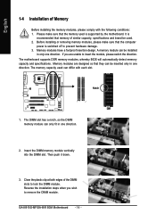
... be installed in only one direction. Notch DDR 1. Insert the DIMM memory module vertically into the DIMM slot. GA-8I915G-MF/GA-8I915GM Motherboard - 14 - The motherboard supports DDR memory modules, whereby BIOS will automatically detect memory capacity and specifications. Reverse the installation steps when you ...please comply with each slot. Before installing or removing memory modules, please make sure that the computer power is supported by the motherboard. Then push it down. 3. English 1-4 Installation of the DIMM slots to lock the DIMM module. Please make sure that...
... be installed in only one direction. Notch DDR 1. Insert the DIMM memory module vertically into the DIMM slot. GA-8I915G-MF/GA-8I915GM Motherboard - 14 - The motherboard supports DDR memory modules, whereby BIOS will automatically detect memory capacity and specifications. Reverse the installation steps when you ...please comply with each slot. Before installing or removing memory modules, please make sure that the computer power is supported by the motherboard. Then push it down. 3. English 1-4 Installation of the DIMM slots to lock the DIMM module. Please make sure that...
Manual
Page 16
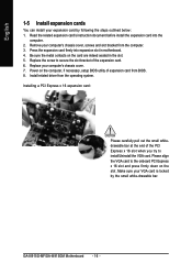
...cover. 7. Installing a PCI Express x 16 expansion card: Please carefully pull out the small whitedrawable bar at the end of the expansion card. 6. GA-8I915G-MF/GA-8I915GM Motherboard - 16 - English 1-5 Install expansion cards You can install your expansion card by the small white-drawable bar. Read the related expansion card's instruction ...the computer, if necessary, setup BIOS utility of expansion card from the operating system. Power on the card are indeed seated in motherboard. 4. Press the expansion card firmly into the computer. 2. Install related driver from BIOS. 8.
...cover. 7. Installing a PCI Express x 16 expansion card: Please carefully pull out the small whitedrawable bar at the end of the expansion card. 6. GA-8I915G-MF/GA-8I915GM Motherboard - 16 - English 1-5 Install expansion cards You can install your expansion card by the small white-drawable bar. Read the related expansion card's instruction ...the computer, if necessary, setup BIOS utility of expansion card from the operating system. Power on the card are indeed seated in motherboard. 4. Press the expansion card firmly into the computer. 2. Install related driver from BIOS. 8.
Manual
Page 18
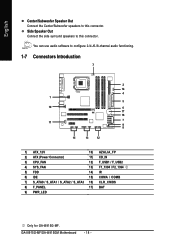
GA-8I915G-MF/GA-8I915GM Motherboard - 18 - English Center/Subwoofer Speaker Out Connect the Center/Subwoofer speakers to this connector. You can use audio software to this connector. Side Speaker Out ...) F_USB1 / F_USB2 4) SYS_FAN 13) F1_1394 / F2_1394 5) FDD 14) IR 6) IDE 15) COMA / COMB 7) S_ATA0 / S_ATA1 / S_ATA2 / S_ATA3 16) CLR_CMOS 8) F_PANEL 17) BAT 9) PWR_LED Only for GA-8I915G-MF.
GA-8I915G-MF/GA-8I915GM Motherboard - 18 - English Center/Subwoofer Speaker Out Connect the Center/Subwoofer speakers to this connector. You can use audio software to this connector. Side Speaker Out ...) F_USB1 / F_USB2 4) SYS_FAN 13) F1_1394 / F2_1394 5) FDD 14) IR 6) IDE 15) COMA / COMB 7) S_ATA0 / S_ATA1 / S_ATA2 / S_ATA3 16) CLR_CMOS 8) F_PANEL 17) BAT 9) PWR_LED Only for GA-8I915G-MF.
Manual
Page 19
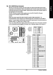
If you use a power supply that all the components on the motherboard. Otherwise, please do not remove it. 42 31 Pin No. 1 2 3 4 Definition GND GND +12V +12V Pin No. Hardware Installation Before connecting the power connector, please ... greater). Please use a 24-pin ATX power supply, please remove the small cover on the power connector on the motherboard and connect tightly. Align the power connector with its proper location on the motherboard before plugging in the power cord ; English 1/2) ATX_12V/ATX (Power Connector) With the use of the power connector...
If you use a power supply that all the components on the motherboard. Otherwise, please do not remove it. 42 31 Pin No. 1 2 3 4 Definition GND GND +12V +12V Pin No. Hardware Installation Before connecting the power connector, please ... greater). Please use a 24-pin ATX power supply, please remove the small cover on the power connector on the motherboard and connect tightly. Align the power connector with its proper location on the motherboard before plugging in the power cord ; English 1/2) ATX_12V/ATX (Power Connector) With the use of the power connector...
Manual
Page 20
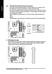
Please remember to connect the power to the cooler to the pin1 position. 34 33 2 1 GA-8I915G-MF/GA-8I915GM Motherboard - 20 - English 3/4) CPU_FAN / SYS_FAN (Cooler Fan Power Connector) The cooler fan power connector supplies a +12V power voltage via a 3-pin/4-pin (only for CPU_FAN) 5) FDD (Floppy ...
Please remember to connect the power to the cooler to the pin1 position. 34 33 2 1 GA-8I915G-MF/GA-8I915GM Motherboard - 20 - English 3/4) CPU_FAN / SYS_FAN (Cooler Fan Power Connector) The cooler fan power connector supplies a +12V power voltage via a 3-pin/4-pin (only for CPU_FAN) 5) FDD (Floppy ...
Manual
Page 22
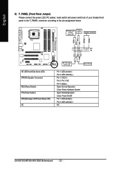
Pin 3: NC Pin 4: Data(-) Open: Normal Operation Close: Reset Hardware System Open: Normal Operation Close: Power On/Off Pin 1: LED anode(+) Pin 2: LED cathode(-) NC GA-8I915G-MF/GA-8I915GM Motherboard - 22 - English 8) F_PANEL (Front Panel Jumper) Please connect the power LED, PC peaker, reset switch and power switch etc of your chassis front panel...
Pin 3: NC Pin 4: Data(-) Open: Normal Operation Close: Reset Hardware System Open: Normal Operation Close: Power On/Off Pin 1: LED anode(+) Pin 2: LED cathode(-) NC GA-8I915G-MF/GA-8I915GM Motherboard - 22 - English 8) F_PANEL (Front Panel Jumper) Please connect the power LED, PC peaker, reset switch and power switch etc of your chassis front panel...
Manual
Page 24
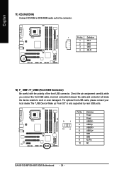
... to work or even damage it. Definition 1 Power 2 Power 9 1 3 USB DX- 4 USB Dy- 10 2 5 USB DX+ 6 USB Dy+ 7 GND 8 GND 9 No Pin 10 NC GA-8I915G-MF/GA-8I915GM Motherboard - 24 - Definition 1 CD-L 2 GND 3 GND 4 CD -R 12) F_ USB1 / F_USB2 (Front USB Connector) Be careful with the polarity of the front USB connector. For...
... to work or even damage it. Definition 1 Power 2 Power 9 1 3 USB DX- 4 USB Dy- 10 2 5 USB DX+ 6 USB Dy+ 7 GND 8 GND 9 No Pin 10 NC GA-8I915G-MF/GA-8I915GM Motherboard - 24 - Definition 1 CD-L 2 GND 3 GND 4 CD -R 12) F_ USB1 / F_USB2 (Front USB Connector) Be careful with the polarity of the front USB connector. For...
Manual
Page 26
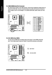
... with the polarity of the COM connector. Default doesn't include the "Shunter" to its default values by this jumper. 1 Open: Normal 1 Short :Clear CMOS GA-8I915G-MF/GA-8I915GM Motherboard - 26 - For optional COM cable, please contact your local dealer. 2 10 1 9 Pin No. 1 2 3 4 5 6 7 8 9 10 Definition NDCD A/BNSIN A/B NSOUT A/B NDTR A/BGND NDSR A/BNRTS A/BNCTS A/BNRI...
... with the polarity of the COM connector. Default doesn't include the "Shunter" to its default values by this jumper. 1 Open: Normal 1 Short :Clear CMOS GA-8I915G-MF/GA-8I915GM Motherboard - 26 - For optional COM cable, please contact your local dealer. 2 10 1 9 Pin No. 1 2 3 4 5 6 7 8 9 10 Definition NDCD A/BNSIN A/B NSOUT A/B NDTR A/BGND NDSR A/BNRTS A/BNCTS A/BNRI...
Manual
Page 29
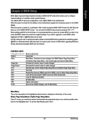
... the user to quickly and easily update or backup BIOS without entering the operating system. @BIOS is turned off, the battery on the motherboard supplies the necessary power to DOS before upgrading BIOS but directly download and update BIOS from BIOS default table Load the Optimized Defaults Q-Flash utility...Menu - Status Page Setup Menu / Option Page Setup Menu Press F1 to its original settings. If you wish to upgrade to a new BIOS, either Gigabyte's Q-Flash or @BIOS utility can enter the BIOS setup screen by pressing "Ctrl + F1". Quit and not save the current BIOS to be used....
... the user to quickly and easily update or backup BIOS without entering the operating system. @BIOS is turned off, the battery on the motherboard supplies the necessary power to DOS before upgrading BIOS but directly download and update BIOS from BIOS default table Load the Optimized Defaults Q-Flash utility...Menu - Status Page Setup Menu / Option Page Setup Menu Press F1 to its original settings. If you wish to upgrade to a new BIOS, either Gigabyte's Q-Flash or @BIOS utility can enter the BIOS setup screen by pressing "Ctrl + F1". Quit and not save the current BIOS to be used....
Manual
Page 30
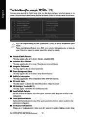
... Set Supervisor Password Set User Password Save & Exit Setup Exit Without Saving KLJI: Select Item F10: Save & Exit Setup Time, Date, Hard Disk Type... GA-8I915G-MF/GA-8I915GM Motherboard - 30 - English The Main Menu (For example: BIOS Ver. : F5) Once you enter Award BIOS CMOS Setup Utility, the Main Menu (as usual. If...
... Set Supervisor Password Set User Password Save & Exit Setup Exit Without Saving KLJI: Select Item F10: Save & Exit Setup Time, Date, Hard Disk Type... GA-8I915G-MF/GA-8I915GM Motherboard - 30 - English The Main Menu (For example: BIOS Ver. : F5) Once you enter Award BIOS CMOS Setup Utility, the Main Menu (as usual. If...
Manual
Page 32
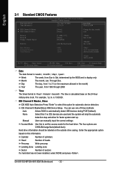
... (or maximum allowed in the month) 1999 to Dec. The time is , , , . Enter the appropriate option based on the 24-hour military-time clock. GA-8I915G-MF/GA-8I915GM Motherboard - 32 - Week The week, from Sun to select this information. IDE Channel 0 Master, Slave IDE HDD Auto-Detection Press "Enter" to Sat, determined by...
... (or maximum allowed in the month) 1999 to Dec. The time is , , , . Enter the appropriate option based on the 24-hour military-time clock. GA-8I915G-MF/GA-8I915GM Motherboard - 32 - Week The week, from Sun to select this information. IDE Channel 0 Master, Slave IDE HDD Auto-Detection Press "Enter" to Sat, determined by...

Manual
Page 33
... errors. BIOS Setup Extended Memory The BIOS determines how much extended memory is typically 512K for systems with 640K or more memory installed on the motherboard, or 640K for Japan Area) Disabled Normal Floppy Drive. (Default value) Drive A Drive B Both Drive A is determined by POST (Power On Self Test) of the... during power up. Memory The category is display-only which is 3 mode Floppy Drive. Floppy 3 Mode Support (for systems with 512K memory installed on the motherboard.
... errors. BIOS Setup Extended Memory The BIOS determines how much extended memory is typically 512K for systems with 640K or more memory installed on the motherboard, or 640K for Japan Area) Disabled Normal Floppy Drive. (Default value) Drive A Drive B Both Drive A is determined by POST (Power On Self Test) of the... during power up. Memory The category is display-only which is 3 mode Floppy Drive. Floppy 3 Mode Support (for systems with 512K memory installed on the motherboard.


