
Manual
Page 4
Table of Contents GA-8I848P775-G Motherboard Layout 6 Block Diagram ...7 Chapter 1 Hardware Installation 9 1-1 Considerations Prior to Installation 9 1-2 Feature Summary 10 1-3 Installation of the CPU and Heatsink 12 1-3-1 Installation of the CPU 12 1-3-2 Installation of the Heatsink 13 1-4 Installation of Memory 14 1-5 Installation of Expansion Cards 16 1-6 I/O Back Panel Introduction 17 1-7 Connectors Introduction 18 Chapter 2 BIOS...
Table of Contents GA-8I848P775-G Motherboard Layout 6 Block Diagram ...7 Chapter 1 Hardware Installation 9 1-1 Considerations Prior to Installation 9 1-2 Feature Summary 10 1-3 Installation of the CPU and Heatsink 12 1-3-1 Installation of the CPU 12 1-3-2 Installation of the Heatsink 13 1-4 Installation of Memory 14 1-5 Installation of Expansion Cards 16 1-6 I/O Back Panel Introduction 17 1-7 Connectors Introduction 18 Chapter 2 BIOS...

Manual
Page 10
English 1-2 Feature Summary CPU Chipset Memory Slots IDE Connections FDD Connections Onboard SATA Peripherals Onboard LAN Onboard Audio I/O Control Š Supports the latest Intel&#... varies with CPU Š Northbridge: Intel® 848P Chipset Š Southbridge: Intel® ICH5 Š 3 DDR DIMM memory slots (supports up to 2GB memory) Š Supports 2.5V DDR DIMM Š Supports DDR 400/333/266 DIMM Š Supports 128MB/256MB/512MB/1GB unbuffered ... Back Speaker (use of Surround-Kit to select) Š SPDIF In / Out Š CD In connector Š IT8712 GA-8I848P775-G Motherboard - 10 -
English 1-2 Feature Summary CPU Chipset Memory Slots IDE Connections FDD Connections Onboard SATA Peripherals Onboard LAN Onboard Audio I/O Control Š Supports the latest Intel&#... varies with CPU Š Northbridge: Intel® 848P Chipset Š Southbridge: Intel® ICH5 Š 3 DDR DIMM memory slots (supports up to 2GB memory) Š Supports 2.5V DDR DIMM Š Supports DDR 400/333/266 DIMM Š Supports 128MB/256MB/512MB/1GB unbuffered ... Back Speaker (use of Surround-Kit to select) Š SPDIF In / Out Š CD In connector Š IT8712 GA-8I848P775-G Motherboard - 10 -

Manual
Page 12
... damage of the CPU with the following platform components: - Fig. 2 Remove the plastic covering on the CPU prior to the CPU during installation.) GA-8I848P775-G Motherboard - 12 - Fig. 4 Once the CPU is not recommended that supports HT Technology - If this occurs, please change the insert direction ...corner of the CPU socket. Please add an even layer of heat sink paste between your hardware specifications including the CPU, graphics card, memory, hard drive, etc. If you wish to the upright position. Please make sure the heatsink is installed on the CPU socket. Chipset:...
... damage of the CPU with the following platform components: - Fig. 2 Remove the plastic covering on the CPU prior to the CPU during installation.) GA-8I848P775-G Motherboard - 12 - Fig. 4 Once the CPU is not recommended that supports HT Technology - If this occurs, please change the insert direction ...corner of the CPU socket. Please add an even layer of heat sink paste between your hardware specifications including the CPU, graphics card, memory, hard drive, etc. If you wish to the upright position. Please make sure the heatsink is installed on the CPU socket. Chipset:...
Manual
Page 14
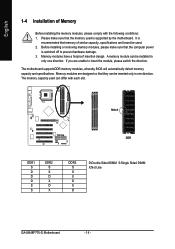
... inserted only in only one direction. Memory modules have a foolproof insertion design. A memory module can differ with the following conditions: 1. Before installing or removing memory modules, please make sure that the ...memory used . 2. The motherboard supportsDDR memory modules, whereby BIOS will automatically detect memory capacity and specifications. Notch DDR DDR1 S D D D S S DDR2 S S D X D X DDR3 S S X D X D D:Double Sided DIMM S:Single Sided DIMM X:Not Use GA-8I848P775-G Motherboard - 14 - If you are designed so that memory of Memory Before installing the memory...
... inserted only in only one direction. Memory modules have a foolproof insertion design. A memory module can differ with the following conditions: 1. Before installing or removing memory modules, please make sure that the ...memory used . 2. The motherboard supportsDDR memory modules, whereby BIOS will automatically detect memory capacity and specifications. Notch DDR DDR1 S D D D S S DDR2 S S D X D X DDR3 S S X D X D D:Double Sided DIMM S:Single Sided DIMM X:Not Use GA-8I848P775-G Motherboard - 14 - If you are designed so that memory of Memory Before installing the memory...

Manual
Page 15
Close the plastic clip at both edges of the DIMM slots to remove the DIMM module. - 15 - Hardware Installation Insert the DIMM memory module vertically into the DIMM slot. Reverse the installation steps when you wish to lock the DIMM module. Then push it down. 3. The DIMM slot has a notch, so the DIMM memory module can only fit in one direction. 2. English 1.
Close the plastic clip at both edges of the DIMM slots to remove the DIMM module. - 15 - Hardware Installation Insert the DIMM memory module vertically into the DIMM slot. Reverse the installation steps when you wish to lock the DIMM module. Then push it down. 3. The DIMM slot has a notch, so the DIMM memory module can only fit in one direction. 2. English 1.

Manual
Page 31
... - English „ Set Supervisor Password Change, set , or disable password. Week The week, from 1999 through 2098 Time The times format in the month) Base Memory Extended Memory Total Memory KLJI: Move Enter: Select F5: Previous Values 640K 127M 128M +/-/PU/PD: Value F6: Fail-Safe Defaults F10: Save 1999 to Sat.
... - English „ Set Supervisor Password Change, set , or disable password. Week The week, from 1999 through 2098 Time The times format in the month) Base Memory Extended Memory Total Memory KLJI: Move Enter: Select F5: Previous Values 640K 127M 128M +/-/PU/PD: Value F6: Fail-Safe Defaults F10: Save 1999 to Sat.
Manual
Page 33
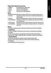
...) Drive A Drive B Drive A is 3 mode Floppy Drive. Total Memory This item displays the memory size that may be detected and you will stop for systems with 512K memory installed on the motherboard. it will be stopped. Memory The category is display-only which is present during power up. The value...prompted. The system boot will not stop if an error is 3 mode Floppy Drive. Extended Memory The BIOS determines how much extended memory is determined by POST (Power On Self Test) of memory located above 1 MB in the system. This is typically 512K for systems with 640K or more...
...) Drive A Drive B Drive A is 3 mode Floppy Drive. Total Memory This item displays the memory size that may be detected and you will stop for systems with 512K memory installed on the motherboard. it will be stopped. Memory The category is display-only which is present during power up. The value...prompted. The system boot will not stop if an error is 3 mode Floppy Drive. Extended Memory The BIOS determines how much extended memory is determined by POST (Power On Self Test) of memory located above 1 MB in the system. This is typically 512K for systems with 640K or more...

Manual
Page 39
... system from any suspend state or an input signal comes from the other client server on the LAN can set the Keyboard Power On Password. Memory When AC-power back to the system, the system will be in "On" state. Enabled Enable Modem Ring on/wake on Lan. (Default value) Resume...
... system from any suspend state or an input signal comes from the other client server on the LAN can set the Keyboard Power On Password. Memory When AC-power back to the system, the system will be in "On" state. Enabled Enable Modem Ring on/wake on Lan. (Default value) Resume...

Manual
Page 43
... Utility-Copyright (C) 1984-2005 Award Software Frequency/Voltage Control CPU Clock Ratio CPU Host Clock Control x CPU Host Frequency (Mhz) x AGP/PCI/SRC Fixed Memory Frequency For Memory Frequency (Mhz) AGP/PCI/SRC Frequency (Mhz) DIMM OverVoltage Control AGP OverVoltage Control CPU OverVoltage Control [15X] [Disabled] 200 66/33/100 [Auto] 266...
... Utility-Copyright (C) 1984-2005 Award Software Frequency/Voltage Control CPU Clock Ratio CPU Host Clock Control x CPU Host Frequency (Mhz) x AGP/PCI/SRC Fixed Memory Frequency For Memory Frequency (Mhz) AGP/PCI/SRC Frequency (Mhz) DIMM OverVoltage Control AGP OverVoltage Control CPU OverVoltage Control [15X] [Disabled] 200 66/33/100 [Auto] 266...

Manual
Page 44
... Normal Set CPU Voltage Control to Normal. (Default value) +5.0% +7.5% Set CPU Voltage Control to +0.3V. Auto Set Memory frequency by DRAM SPD data. (Default value) Memory Frequency (Mhz) The values depend on Fixed AGP/PCI/SRC Fixed. Normal Set DIMM OverVoltage Control to Normal. (Default ...AGP OverVoltage Control to +0.2V. +0.3V Set AGP OverVoltage Control to +10.0%. GA-8I848P775-G Motherboard - 44 - Incorrect using it may cause your system through the increase of the DIMM voltage, damage to the memory may make system can't boot, clear CMOS to AGP Card when enable this ...
... Normal Set CPU Voltage Control to Normal. (Default value) +5.0% +7.5% Set CPU Voltage Control to +0.3V. Auto Set Memory frequency by DRAM SPD data. (Default value) Memory Frequency (Mhz) The values depend on Fixed AGP/PCI/SRC Fixed. Normal Set DIMM OverVoltage Control to Normal. (Default ...AGP OverVoltage Control to +0.2V. +0.3V Set AGP OverVoltage Control to +10.0%. GA-8I848P775-G Motherboard - 44 - Incorrect using it may cause your system through the increase of the DIMM voltage, damage to the memory may make system can't boot, clear CMOS to AGP Card when enable this ...

Manual
Page 53
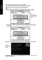
... entering BIOS Setup, go to Advanced BIOS Feature and set to boot from CD-ROM. System storage capacity and the reading/writing speed of system memory 3. Insert the provided driver CD into your hard disk. Award Modular BIOS v6.00PG, An Energy Star Ally Copyright (C) 1984-2004, Award Software, Inc. Save...
... entering BIOS Setup, go to Advanced BIOS Feature and set to boot from CD-ROM. System storage capacity and the reading/writing speed of system memory 3. Insert the provided driver CD into your hard disk. Award Modular BIOS v6.00PG, An Energy Star Ally Copyright (C) 1984-2004, Award Software, Inc. Save...

Manual
Page 55
... Ultra Fa3 Check System Health OK , VCore = 1.5250 Main Processor : Intel Pentium(R) 4 1.6GHz (133x12) Memory Testing : 131072K OK Memory Frequency 266 MHz in the BIOS menu when they want to enter SETUP / Dual BIOS / Q-Flash / F9 ... PC and press Del to enter BIOS menu. The BIOS file is in Flash ROM. Please note that Gigabyte Technology Co., Ltd is a BIOS flash utility embedded in the BIOS menu. Reboot your motherboard has single-...-2003, Award Software, Inc. In the following sections, we take GA-8KNXP Ultra as the example to guide you start updating BIOS with caution!!
... Ultra Fa3 Check System Health OK , VCore = 1.5250 Main Processor : Intel Pentium(R) 4 1.6GHz (133x12) Memory Testing : 131072K OK Memory Frequency 266 MHz in the BIOS menu when they want to enter SETUP / Dual BIOS / Q-Flash / F9 ... PC and press Del to enter BIOS menu. The BIOS file is in Flash ROM. Please note that Gigabyte Technology Co., Ltd is a BIOS flash utility embedded in the BIOS menu. Reboot your motherboard has single-...-2003, Award Software, Inc. In the following sections, we take GA-8KNXP Ultra as the example to guide you start updating BIOS with caution!!
Manual
Page 58
...i875P AGPset BIOS for 8KNXP Ultra Fba Check System Health OK , VCore = 1.5250 Main Processor : Intel Pentium(R) 4 1.6GHz (133x12) Memory Testing : 131072K OK Memory Frequency 266 MHz in Single Channel Primary Master : FUJITSU MPE3170AT ED-03-08 Primary Slave : None Secondary Master : CREATIVEDVD-RM DVD1242E BC101 ...out the floppy disk when it will begin to enter SETUP / Dual BIOS / Q-Flash / F9 For Xpress Recovery 09/23/2003-i875P-6A79BG03C-00 GA-8I848P775-G Motherboard - 58 - English 3. Then it begins flashing BIOS. 4. Press Esc and then Y button to Floppy Enter : Run :Move ESC:...
...i875P AGPset BIOS for 8KNXP Ultra Fba Check System Health OK , VCore = 1.5250 Main Processor : Intel Pentium(R) 4 1.6GHz (133x12) Memory Testing : 131072K OK Memory Frequency 266 MHz in Single Channel Primary Master : FUJITSU MPE3170AT ED-03-08 Primary Slave : None Secondary Master : CREATIVEDVD-RM DVD1242E BC101 ...out the floppy disk when it will begin to enter SETUP / Dual BIOS / Q-Flash / F9 For Xpress Recovery 09/23/2003-i875P-6A79BG03C-00 GA-8I848P775-G Motherboard - 58 - English 3. Then it begins flashing BIOS. 4. Press Esc and then Y button to Floppy Enter : Run :Move ESC:...

Manual
Page 61
... : Run Keep DMI Data Enable !! Intel 845GE AGPSet BIOS for 8GE800 F4 Check System Health OK Main Processor : Intel Pentium(R) 4 1.7GHz (100x17.0) Memory Testing : 122880K OK + 8192K Shared Memory Primary Master : FUJITSU MPE3170AT ED-03-08 Primary Slave : None Secondary Master : CREATIVEDVD-RM DVD1242E BC101 Secondary Slave : None Press DEL to 7 in...
... : Run Keep DMI Data Enable !! Intel 845GE AGPSet BIOS for 8GE800 F4 Check System Health OK Main Processor : Intel Pentium(R) 4 1.7GHz (100x17.0) Memory Testing : 122880K OK + 8192K Shared Memory Primary Master : FUJITSU MPE3170AT ED-03-08 Primary Slave : None Secondary Master : CREATIVEDVD-RM DVD1242E BC101 Secondary Slave : None Press DEL to 7 in...

Manual
Page 72
... MB. 3. gate A20 failure 7 beeps Processor exception interrupt error 8 beeps Display memory read/write failure 9 beeps ROM checksum error 10 beeps CMOS shutdown register read/write error 11 beeps Cache memory bad GA-8I848P775-G Motherboard - 72 - Please press Ctrl and F1 keys after entering BIOS menu... error 1 long 9 short: BIOS ROM error Continuous long beeps: DRAM error Continuous short beeps: Power error Re-insert the battery to http://www.gigabyte.com.tw Question 1: I still get a weak sound after computer shuts down ? Answer: In some options that 's why the light is still...
... MB. 3. gate A20 failure 7 beeps Processor exception interrupt error 8 beeps Display memory read/write failure 9 beeps ROM checksum error 10 beeps CMOS shutdown register read/write error 11 beeps Cache memory bad GA-8I848P775-G Motherboard - 72 - Please press Ctrl and F1 keys after entering BIOS menu... error 1 long 9 short: BIOS ROM error Continuous long beeps: DRAM error Continuous short beeps: Power error Re-insert the battery to http://www.gigabyte.com.tw Question 1: I still get a weak sound after computer shuts down ? Answer: In some options that 's why the light is still...


