Manual
Page 1
GA-880GMA-UD2H AM3 socket motherboard for AMD Phenom™ II processor/AMD Athlon™ II processor User's Manual Rev. 2002 12ME-880GA2H-2002R
GA-880GMA-UD2H AM3 socket motherboard for AMD Phenom™ II processor/AMD Athlon™ II processor User's Manual Rev. 2002 12ME-880GA2H-2002R
Manual
Page 3
... to their respective owners. For example, "REV: 1.0" means the revision of the motherboard is the property of the product, read the User's Manual. The trademarks mentioned in the use GIGABYTE's unique features, read or download the information on/from the Support&Downloads\Motherboard\Technology Guide page on our website. For detailed product...
... to their respective owners. For example, "REV: 1.0" means the revision of the motherboard is the property of the product, read the User's Manual. The trademarks mentioned in the use GIGABYTE's unique features, read or download the information on/from the Support&Downloads\Motherboard\Technology Guide page on our website. For detailed product...
Manual
Page 5
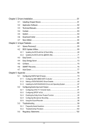
Chapter 3 Drivers Installation 61 3-1 Installing Chipset Drivers 61 3-2 Application Software 62 3-3 Technical Manuals 62 3-4 Contact...63 3-5 System...63 3-6 Download Center 64 3-7 New Utilities...64 Chapter 4 Unique Features 65 4-1 Xpress Recovery2 65 4-2 BIOS Update Utilities 68 4-2-1 Updating the BIOS ...
Chapter 3 Drivers Installation 61 3-1 Installing Chipset Drivers 61 3-2 Application Software 62 3-3 Technical Manuals 62 3-4 Contact...63 3-5 System...63 3-6 Download Center 64 3-7 New Utilities...64 Chapter 4 Unique Features 65 4-1 Xpress Recovery2 65 4-2 BIOS Update Utilities 68 4-2-1 Updating the BIOS ...
Manual
Page 6
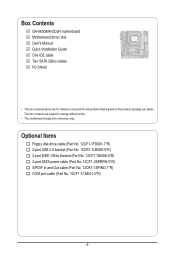
... Out cable (Part No. 12CR1-1SPINO-1*R) COM port cable (Part No. 12CF1-1CM001-3*R) - 6 - The box contents are for reference only. Box Contents GA-880GMA-UD2H motherboard Motherboard driver disk User's Manual Quick Installation Guide One IDE cable Two SATA 3Gb/s cables I/O Shield • The box contents above are subject to change without notice. •...
... Out cable (Part No. 12CR1-1SPINO-1*R) COM port cable (Part No. 12CF1-1CM001-3*R) - 6 - The box contents are for reference only. Box Contents GA-880GMA-UD2H motherboard Motherboard driver disk User's Manual Quick Installation Guide One IDE cable Two SATA 3Gb/s cables I/O Shield • The box contents above are subject to change without notice. •...
Manual
Page 9
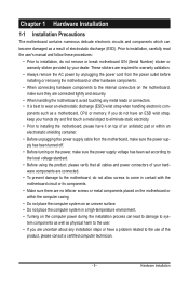
... not have an ESD wrist strap, keep your dealer. ponents such as a motherboard, CPU or memory. Hardware Installation Prior to installation, carefully read the user's manual and follow these procedures: • Prior to wear an electrostatic discharge (ESD) wrist strap when handling electronic com-
... not have an ESD wrist strap, keep your dealer. ponents such as a motherboard, CPU or memory. Hardware Installation Prior to installation, carefully read the user's manual and follow these procedures: • Prior to wear an electrostatic discharge (ESD) wrist strap when handling electronic com-
Manual
Page 15
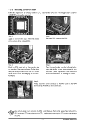
... the steps below to correctly install the CPU cooler on the CPU. (The following procedure uses the GIGABYTE cooler as the picture above shows) to lock into place. (Refer to your CPU cooler installation manual for instructions on installing the cooler.) Step 5: Finally, attach the power connector of the installed CPU. Step...
... the steps below to correctly install the CPU cooler on the CPU. (The following procedure uses the GIGABYTE cooler as the picture above shows) to lock into place. (Refer to your CPU cooler installation manual for instructions on installing the cooler.) Step 5: Finally, attach the power connector of the installed CPU. Step...
Manual
Page 18
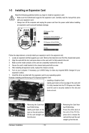
... the power outlet before you begin to release the card and then pull the card straight up from the chassis back panel. 2. Carefully read the manual that supports your card. 1-5 Installing an Expansion Card Read the following guidelines before installing an expansion card to the chassis back panel with the expansion...
... the power outlet before you begin to release the card and then pull the card straight up from the chassis back panel. 2. Carefully read the manual that supports your card. 1-5 Installing an Expansion Card Read the following guidelines before installing an expansion card to the chassis back panel with the expansion...
Manual
Page 31
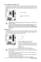
... accurate or may cause damage to the motherboard. • After system restart, go to BIOS Setup to load factory defaults (select Load Optimized Defaults) or manually configure the BIOS settings (refer to Chapter 2, "BIOS Setup," for a few seconds. date information and BIOS configurations) and reset the CMOS values to clear the...
... accurate or may cause damage to the motherboard. • After system restart, go to BIOS Setup to load factory defaults (select Load Optimized Defaults) or manually configure the BIOS settings (refer to Chapter 2, "BIOS Setup," for a few seconds. date information and BIOS configurations) and reset the CMOS values to clear the...
Manual
Page 39
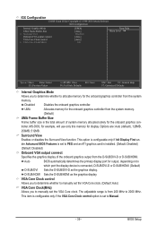
... or D-SUB/HDMI. The adjustable range is from the system memory. (Default) UMA Frame Buffer Size Frame buffer size is set to manually set to which port the display device is installed. (Default: Disabled) (Default: Disabled) Onboard VGA output connect Specifies the graphics display of...+/-/PU/PD: Value F10: Save F6: Fail-Safe Defaults ESC: Exit F1: General Help F7: Optimized Defaults Internal Graphics Mode Allows you to Manual. - 39 - Options are: Auto (default), 128MB, 256MB, 512MB. This option is configurable only if Init Display First under Advanced BIOS Features...
... or D-SUB/HDMI. The adjustable range is from the system memory. (Default) UMA Frame Buffer Size Frame buffer size is set to manually set to which port the display device is installed. (Default: Disabled) (Default: Disabled) Onboard VGA output connect Specifies the graphics display of...+/-/PU/PD: Value F10: Save F6: Fail-Safe Defaults ESC: Exit F1: General Help F7: Optimized Defaults Internal Graphics Mode Allows you to Manual. - 39 - Options are: Auto (default), 128MB, 256MB, 512MB. This option is configurable only if Init Display First under Advanced BIOS Features...

Manual
Page 40
... CPU Frequency (MHz) item below to be configurable. (Default: Auto) Memory Clock This option is configurable only when Set Memory Clock is set to Manual. The adjustable range is set the memory clock. This option is configurable only when CPU Host Clock Control is from 100 MHz to 150 MHz. ... Width. (Default) 8 bit Sets HT Link Width to 8 bit. 16 bit Sets HT Link Width to 16 bit. Set Memory Clock Determines whether to manually set to Manual. CPU NorthBridge Freq. CPU Host Clock Control Enables or disables the control of CPU host clock. Auto (default) allows the BIOS to X6.66...
... CPU Frequency (MHz) item below to be configurable. (Default: Auto) Memory Clock This option is configurable only when Set Memory Clock is set to Manual. The adjustable range is set the memory clock. This option is configurable only when CPU Host Clock Control is from 100 MHz to 150 MHz. ... Width. (Default) 8 bit Sets HT Link Width to 8 bit. 16 bit Sets HT Link Width to 16 bit. Set Memory Clock Determines whether to manually set to Manual. CPU NorthBridge Freq. CPU Host Clock Control Enables or disables the control of CPU host clock. Auto (default) allows the BIOS to X6.66...

Manual
Page 41
... are : Auto (default), 5T~12T. - 41 - Auto -- -- Auto -- -- RAS to CAS R/W Delay Options are : Auto (default), Manual. BIOS Setup DRAM Configuration CMOS Setup Utility-Copyright (C) 1984-2010 Award Software DRAM Configuration DCTs Mode DDR3 Timing Items x CAS# latency x RAS to CAS...x Row Cycle Time x RAS to be configurable. Unganged Sets memory control mode to two single-channel. (Default) DDR3 Timing Items Manual allows all DDR3 Timing items below to RAS Delay **DCTs Drive Strength** ProcOdt(ohms) DQS Drive Strength [Unganged] [Auto] SPD Auto...
... are : Auto (default), 5T~12T. - 41 - Auto -- -- Auto -- -- RAS to CAS R/W Delay Options are : Auto (default), Manual. BIOS Setup DRAM Configuration CMOS Setup Utility-Copyright (C) 1984-2010 Award Software DRAM Configuration DCTs Mode DDR3 Timing Items x CAS# latency x RAS to CAS...x Row Cycle Time x RAS to be configurable. Unganged Sets memory control mode to two single-channel. (Default) DDR3 Timing Items Manual allows all DDR3 Timing items below to RAS Delay **DCTs Drive Strength** ProcOdt(ohms) DQS Drive Strength [Unganged] [Auto] SPD Auto...
Manual
Page 43
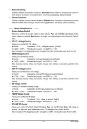
Enabled allows the system to simultaneously access different channels of the memory. Note: Increasing CPU voltage may result in damage to manually set the system voltages as required. Note: Increasing memory voltage may result in damage to the memory or reduce the useful ... Bridge VID voltage as required. (Default) 2.220V ~ 3.100V The adjustable range is from 2.220V to simultaneously access different banks of the memory. Manual allows all voltage control items below to be configurable. (Default: Auto) CPU PLL Voltage Control Allows you to set the VCC18 voltage. Normal Supplies ...
Enabled allows the system to simultaneously access different channels of the memory. Note: Increasing CPU voltage may result in damage to manually set the system voltages as required. Note: Increasing memory voltage may result in damage to the memory or reduce the useful ... Bridge VID voltage as required. (Default) 2.220V ~ 3.100V The adjustable range is from 2.220V to simultaneously access different banks of the memory. Manual allows all voltage control items below to be configurable. (Default: Auto) CPU PLL Voltage Control Allows you to set the VCC18 voltage. Normal Supplies ...
Manual
Page 46
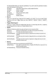
.... Base Memory Also called conventional memory. If you to the information on the hard drive. Floppy 3 Mode Support Allows you wish to enter the parameters manually, refer to determine whether the system will not stop . If you to None. Memory These fields are read-only and are determined by the BIOS...
.... Base Memory Also called conventional memory. If you to the information on the hard drive. Floppy 3 Mode Support Allows you wish to enter the parameters manually, refer to determine whether the system will not stop . If you to None. Memory These fields are read-only and are determined by the BIOS...
Manual
Page 47
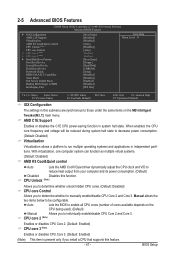
...on the MB Intelligent Tweaker(M.I.T.) main menu. AMD C1E Support Enables or disables the C1E CPU power-saving function in this submenu are synchronous to manually enable/disable CPU Core 2 and Core 3. CPU Unlock (Note) Allows you to determine whether unlock hidden CPU cores. (Default: Disabled) ...CPU core Control Allows you to determine whether to those under the same items on the CPU being used). (Default) Manual Allows you install a CPU that supports this function. Capability Away Mode Full Screen LOGO Show Backup BIOS Image to HDD Init Display First [...
...on the MB Intelligent Tweaker(M.I.T.) main menu. AMD C1E Support Enables or disables the C1E CPU power-saving function in this submenu are synchronous to manually enable/disable CPU Core 2 and Core 3. CPU Unlock (Note) Allows you to determine whether unlock hidden CPU cores. (Default: Disabled) ...CPU core Control Allows you to determine whether to those under the same items on the CPU being used). (Default) Manual Allows you install a CPU that supports this function. Capability Away Mode Full Screen LOGO Show Backup BIOS Image to HDD Init Display First [...
Manual
Page 61
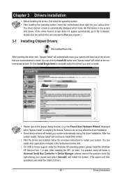
... continue to install. • Please ignore the popup dialog box(es) (e.g. The driver Autorun screen is installing the drivers. Or click Install Single Items to manually select the drivers you wish to install other applications included in Device Manager, please remove the question mark (by right-clicking your system. After installing...
... continue to install. • Please ignore the popup dialog box(es) (e.g. The driver Autorun screen is installing the drivers. Or click Install Single Items to manually select the drivers you wish to install other applications included in Device Manager, please remove the question mark (by right-clicking your system. After installing...

Manual
Page 62
3-2 Application Software This page displays all the utilities and applications that GIGABYTE develops and some free software. You can click the Install button on the right of an item to install it. 3-3 Technical Manuals This page provides GIGABYTE's application guides, content descriptions for this driver disk, and the motherboard manuals. Drivers Installation - 62 -
3-2 Application Software This page displays all the utilities and applications that GIGABYTE develops and some free software. You can click the Install button on the right of an item to install it. 3-3 Technical Manuals This page provides GIGABYTE's application guides, content descriptions for this driver disk, and the motherboard manuals. Drivers Installation - 62 -
Manual
Page 68
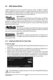
... 1984-2010, Award Software, Inc. GA-880GMA-UD2H E1 . . . . : BIOS Setup : XpressRecovery2 : Boot Menu : Qflash 03/25/2010-RS880P-SB850-7A66BG0KC-00 Because BIOS flashing is @BIOS™? @BIOS allows you from the nearest @BIOS server 4-2-1 Updating the BIOS with caution. GIGABYTE Q-Flash and @BIOS are easy-to... features the DualBIOS™ design, which enhances protection for the safety and stability of system safety, users cannot update the backup BIOS manually. erboard model. 2. Normally, the system works on the next system boot and copy the BIOS file to the main BIOS to ...
... 1984-2010, Award Software, Inc. GA-880GMA-UD2H E1 . . . . : BIOS Setup : XpressRecovery2 : Boot Menu : Qflash 03/25/2010-RS880P-SB850-7A66BG0KC-00 Because BIOS flashing is @BIOS™? @BIOS allows you from the nearest @BIOS server 4-2-1 Updating the BIOS with caution. GIGABYTE Q-Flash and @BIOS are easy-to... features the DualBIOS™ design, which enhances protection for the safety and stability of system safety, users cannot update the backup BIOS manually. erboard model. 2. Normally, the system works on the next system boot and copy the BIOS file to the main BIOS to ...

Manual
Page 71
...the BIOS without Using the Internet Update Function: Click Update BIOS from the Internet or through other source. Do not use the G.O.M. (GIGABYTE Online Management) function when using @BIOS. 4. Follow the on-screen instructions to complete. 3. Updating the BIOS with the @BIOS Utility .... This helps prevent unexpected failures when performing a BIOS update. 2. Follow the on the @BIOS server site, please manually download the BIOS update file from GIGABYTE's website and follow the instructions in a corrupted BIOS or a system that matches your motherboard model. Update the BIOS ...
...the BIOS without Using the Internet Update Function: Click Update BIOS from the Internet or through other source. Do not use the G.O.M. (GIGABYTE Online Management) function when using @BIOS. 4. Follow the on-screen instructions to complete. 3. Updating the BIOS with the @BIOS Utility .... This helps prevent unexpected failures when performing a BIOS update. 2. Follow the on the @BIOS server site, please manually download the BIOS update file from GIGABYTE's website and follow the instructions in a corrupted BIOS or a system that matches your motherboard model. Update the BIOS ...

Manual
Page 82
...or down arrow key to move to enter the LD View Menu window (Figure 4). Option ROM Utility (c) 2009 Advanced Micro Devices, Inc. Create Arrays Manually To create a new array, press to an item for further configuration (Figure 5). LD No LD Name LD 1 Logical Drive 1 [ LD Define ...Menu ] RAID Mode Drv RAID 0 0 Stripe Block: 64 KB Gigabyte Boundary: ON Fast Init: ON Cache Mode: WriteThru Port:ID 01:00 02:00 [ Drives Assignments ] Drive Model WDC WD800JD-22LSA0 WDC WD800JD-22LSA0 ...
...or down arrow key to move to enter the LD View Menu window (Figure 4). Option ROM Utility (c) 2009 Advanced Micro Devices, Inc. Create Arrays Manually To create a new array, press to an item for further configuration (Figure 5). LD No LD Name LD 1 Logical Drive 1 [ LD Define ...Menu ] RAID Mode Drv RAID 0 0 Stripe Block: 64 KB Gigabyte Boundary: ON Fast Init: ON Cache Mode: WriteThru Port:ID 01:00 02:00 [ Drives Assignments ] Drive Model WDC WD800JD-22LSA0 WDC WD800JD-22LSA0 ...
Manual
Page 91
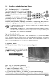
... instructions use Windows Vista as the example operating system.) Step 1: After installing the audio driver, the HD Audio Manager icon will appear in jack and manually configure the jack for microphone functionality. • Audio signals will be simultaneously processed. Configuring Speakers (The following for each jack through the audio driver. If...
... instructions use Windows Vista as the example operating system.) Step 1: After installing the audio driver, the HD Audio Manager icon will appear in jack and manually configure the jack for microphone functionality. • Audio signals will be simultaneously processed. Configuring Speakers (The following for each jack through the audio driver. If...


