Manual
Page 2
Motherboard GA-880GM-USB3L Mar. 1, 2011 Motherboard GA-880GM-USB3L Mar. 1, 2011
Motherboard GA-880GM-USB3L Mar. 1, 2011 Motherboard GA-880GM-USB3L Mar. 1, 2011
Manual
Page 3
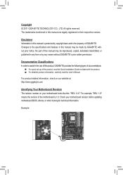
...2011 GIGA-BYTE TECHNOLOGY CO., LTD. Disclaimer Information in the use of this product, GIGABYTE provides the following types of documentations: For quick set-up of the motherboard is the property of this manual may be reproduced, copied, translated, transmitted, or ... information, check on our website at: http://www.gigabyte.com Identifying Your Motherboard Revision The revision number on your motherboard revision before updating motherboard BIOS, drivers, or when looking for technical information. Check your motherboard looks like this manual may be made by any ...
...2011 GIGA-BYTE TECHNOLOGY CO., LTD. Disclaimer Information in the use of this product, GIGABYTE provides the following types of documentations: For quick set-up of the motherboard is the property of this manual may be reproduced, copied, translated, transmitted, or ... information, check on our website at: http://www.gigabyte.com Identifying Your Motherboard Revision The revision number on your motherboard revision before updating motherboard BIOS, drivers, or when looking for technical information. Check your motherboard looks like this manual may be made by any ...
Manual
Page 4
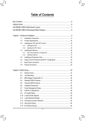
Table of Contents Box Contents...6 Optional Items...6 GA-880GM-USB3L Motherboard Layout 7 GA-880GM-USB3L Motherboard Block Diagram 8 Chapter 1 Hardware Installation 9 1-1 Installation Precautions 9 1-2 Product Specifications 10 1-3 Installing the CPU and CPU Cooler 13 1-3-1 Installing the CPU 13 1-3-2 Installing the CPU Cooler ...
Table of Contents Box Contents...6 Optional Items...6 GA-880GM-USB3L Motherboard Layout 7 GA-880GM-USB3L Motherboard Block Diagram 8 Chapter 1 Hardware Installation 9 1-1 Installation Precautions 9 1-2 Product Specifications 10 1-3 Installing the CPU and CPU Cooler 13 1-3-1 Installing the CPU 13 1-3-2 Installing the CPU Cooler ...
Manual
Page 6
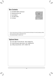
The box contents are for reference only. Box Contents GA-880GM-USB3L motherboard Motherboard driver disk User's Manual Two SATA cables I/O Shield • The box contents above are subject to change without notice. • The motherboard image is for reference only and the actual items shall depend on the product package you obtain. Optional Items 2-port USB 2.0 bracket (Part No. 12CR1-1UB030-5*R) 2-port SATA power cable (Part No. 12CF1-2SERPW-0*R) COM port cable (Part No. 12CF1-1CM001-3*R) - 6 -
The box contents are for reference only. Box Contents GA-880GM-USB3L motherboard Motherboard driver disk User's Manual Two SATA cables I/O Shield • The box contents above are subject to change without notice. • The motherboard image is for reference only and the actual items shall depend on the product package you obtain. Optional Items 2-port USB 2.0 bracket (Part No. 12CR1-1UB030-5*R) 2-port SATA power cable (Part No. 12CF1-2SERPW-0*R) COM port cable (Part No. 12CF1-1CM001-3*R) - 6 -
Manual
Page 7
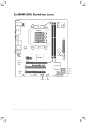
GA-880GM-USB3L Motherboard Layout DVI VGA KB_MS_USB ATX_12V Socket AM3+ CPU_FAN M_BIOS B_BIOS iTE IT8720 HDMI USB ATX R_USB AUDIO LAN Etron EJ168 F_AUDIO Realtek RTL8111E PCIEX1 AMD 880G PCIEX16 PCI1 GA-880GM-USB3L PCI2 CODEC SPDIF_O SYS_FAN F_USB2 F_USB1 DDR3_1 DDR3_2 BAT CLR_CMOS COM AMD SB710 SATA2_0 F_PANEL SATA2_3 SATA2_2 SATA2_1 - 7 -
GA-880GM-USB3L Motherboard Layout DVI VGA KB_MS_USB ATX_12V Socket AM3+ CPU_FAN M_BIOS B_BIOS iTE IT8720 HDMI USB ATX R_USB AUDIO LAN Etron EJ168 F_AUDIO Realtek RTL8111E PCIEX1 AMD 880G PCIEX16 PCI1 GA-880GM-USB3L PCI2 CODEC SPDIF_O SYS_FAN F_USB2 F_USB1 DDR3_1 DDR3_2 BAT CLR_CMOS COM AMD SB710 SATA2_0 F_PANEL SATA2_3 SATA2_2 SATA2_1 - 7 -
Manual
Page 8
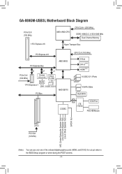
GA-880GM-USB3L Motherboard Block Diagram PCIe CLK (100 MHz) AM3+/AM3 CPU CPU CLK+/- (200 MHz) DDR3 1666(O.C.)/1333/1066 MHz Dual Channel Memory 1 PCI Express x16 Hyper ...
GA-880GM-USB3L Motherboard Block Diagram PCIe CLK (100 MHz) AM3+/AM3 CPU CPU CLK+/- (200 MHz) DDR3 1666(O.C.)/1333/1066 MHz Dual Channel Memory 1 PCI Express x16 Hyper ...

Manual
Page 9
..., please verify that all cables and power connectors of your hardware components are connected. • To prevent damage to the motherboard, do not remove or break motherboard S/N (Serial Number) sticker or warranty sticker provided by your hands dry and first touch a metal object to eliminate static electricity.... • Prior to installing the motherboard, please have it on top of an antistatic pad or within the computer casing. • Do not place the computer system on an...
..., please verify that all cables and power connectors of your hardware components are connected. • To prevent damage to the motherboard, do not remove or break motherboard S/N (Serial Number) sticker or warranty sticker provided by your hands dry and first touch a metal object to eliminate static electricity.... • Prior to installing the motherboard, please have it on top of an antistatic pad or within the computer casing. • Do not place the computer system on an...

Manual
Page 12
... Center ŠŠ Support for Xpress Install ŠŠ Support for Xpress Recovery2 ŠŠ Support for EasyTune * Available functions in EasyTune may differ by motherboard model. ŠŠ Support for Smart Recovery ŠŠ Support for Auto Green ŠŠ Support for ON/OFF Charge ŠŠ Support for Cloud...
... Center ŠŠ Support for Xpress Install ŠŠ Support for Xpress Recovery2 ŠŠ Support for EasyTune * Available functions in EasyTune may differ by motherboard model. ŠŠ Support for Smart Recovery ŠŠ Support for Auto Green ŠŠ Support for ON/OFF Charge ŠŠ Support for Cloud...
Manual
Page 13
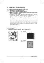
... standard requirements for the latest CPU support list.) • Always turn on the computer if the CPU cooler is not recommended that the motherboard supports the CPU. (Go to GIGABYTE's website for the peripherals. If you may occur. • Set the CPU host frequency in accordance with the CPU specifications. 1-3 Installing the...
... standard requirements for the latest CPU support list.) • Always turn on the computer if the CPU cooler is not recommended that the motherboard supports the CPU. (Go to GIGABYTE's website for the peripherals. If you may occur. • Set the CPU host frequency in accordance with the CPU specifications. 1-3 Installing the...

Manual
Page 14
Follow the steps below to correctly install the CPU into the motherboard CPU socket. • Before installing the CPU, make sure to turn off the computer and unplug the power cord from the power outlet to prevent ...
Follow the steps below to correctly install the CPU into the motherboard CPU socket. • Before installing the CPU, make sure to turn off the computer and unplug the power cord from the power outlet to prevent ...

Manual
Page 15
... Apply an even and thin layer of thermal grease on the surface of the CPU cooler to the CPU fan header (CPU_FAN) on the motherboard. Step 2: Place the CPU cooler on the retention frame. Hardware Installation Inadequately removing the CPU cooler may adhere to the CPU. 1-3-2 Installing... the CPU Cooler Follow the steps below to correctly install the CPU cooler on the CPU. (The following procedure uses the GIGABYTE cooler as the picture above shows) to lock into place. (Refer to your CPU cooler installation manual for instructions on installing the cooler.)...
... Apply an even and thin layer of thermal grease on the surface of the CPU cooler to the CPU fan header (CPU_FAN) on the motherboard. Step 2: Place the CPU cooler on the retention frame. Hardware Installation Inadequately removing the CPU cooler may adhere to the CPU. 1-3-2 Installing... the CPU Cooler Follow the steps below to correctly install the CPU cooler on the CPU. (The following procedure uses the GIGABYTE cooler as the picture above shows) to lock into place. (Refer to your CPU cooler installation manual for instructions on installing the cooler.)...

Manual
Page 16
...two memory modules, it is recommended that memory of the same capacity, brand, speed, and chips be used . It is recommended that the motherboard supports the memory. The two DDR3 memory sockets are unable to insert the memory, switch the direction. 1-4-1 Dual Channel Memory Configuration This... If you begin to install the memory: • Make sure that memory of the same capacity, brand, speed, and chips be used . (Go to GIGABYTE's website for the latest supported memory speeds and memory modules.) • Always turn off the computer and unplug the power cord from the power outlet...
...two memory modules, it is recommended that memory of the same capacity, brand, speed, and chips be used . It is recommended that the motherboard supports the memory. The two DDR3 memory sockets are unable to insert the memory, switch the direction. 1-4-1 Dual Channel Memory Configuration This... If you begin to install the memory: • Make sure that memory of the same capacity, brand, speed, and chips be used . (Go to GIGABYTE's website for the latest supported memory speeds and memory modules.) • Always turn off the computer and unplug the power cord from the power outlet...

Manual
Page 17
..., make sure to turn off the computer and unplug the power cord from the power outlet to prevent damage to install DDR3 DIMMs on this motherboard. DDR3 and DDR2 DIMMs are not compatible to each other or DDR DIMMs. Be sure to the memory module. Spread the retaining clips at both...
..., make sure to turn off the computer and unplug the power cord from the power outlet to prevent damage to install DDR3 DIMMs on this motherboard. DDR3 and DDR2 DIMMs are not compatible to each other or DDR DIMMs. Be sure to the memory module. Spread the retaining clips at both...
Manual
Page 18
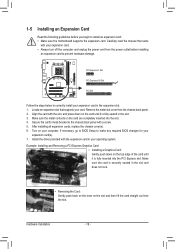
... turn off the computer and unplug the power cord from the power outlet before you begin to install an expansion card: • Make sure the motherboard supports the expansion card. Turn on the slot and then lift the card straight out from the chassis back panel. 2. Example: Installing and Removing a PCI...
... turn off the computer and unplug the power cord from the power outlet before you begin to install an expansion card: • Make sure the motherboard supports the expansion card. Turn on the slot and then lift the card straight out from the chassis back panel. 2. Example: Installing and Removing a PCI...
Manual
Page 19
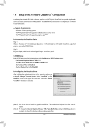
...and ensure the Enable CrossFire™ check box is selected. (Note 1) You do not have to install the graphics card driver if the motherboard chipset driver has been installed. (Note 2) To change the Internal Graphics Mode or UMA Frame Buffer Size setting in BIOS Setup, be ... BIOS Features menu: - Select CrossFire™ on the Graphics menu on configuring an ATI Hybrid CrossFireX system. An ATI Hybrid CrossFireX-supported motherboard and correct driver - Connecting the Graphics Cards Step 1: Observe the steps in the operating system first. - 19 - Configuring the Graphics Driver ...
...and ensure the Enable CrossFire™ check box is selected. (Note 1) You do not have to install the graphics card driver if the motherboard chipset driver has been installed. (Note 2) To change the Internal Graphics Mode or UMA Frame Buffer Size setting in BIOS Setup, be ... BIOS Features menu: - Select CrossFire™ on the Graphics menu on configuring an ATI Hybrid CrossFireX system. An ATI Hybrid CrossFireX-supported motherboard and correct driver - Connecting the Graphics Cards Step 1: Observe the steps in the operating system first. - 19 - Configuring the Graphics Driver ...
Manual
Page 21
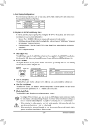
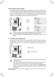
...Audio." • When removing the cable connected to a back panel connector, first remove the cable from your device and then remove it from the motherboard. • When removing the cable, pull it side to side to connect front speakers in devices such as a USB keyboard/mouse, USB printer... occurring Line In Jack (Blue) The default line in jack. This jack can be connected to the USB 2.0/1.1 specification. Dual Display Configurations: This motherboard provides three ports for a headphone or 2-channel speaker. Line Out Jack (Green) The default line out jack. Mic In Jack (Pink) The ...
...Audio." • When removing the cable connected to a back panel connector, first remove the cable from your device and then remove it from the motherboard. • When removing the cable, pull it side to side to connect front speakers in devices such as a USB keyboard/mouse, USB printer... occurring Line In Jack (Blue) The default line in jack. This jack can be connected to the USB 2.0/1.1 specification. Dual Display Configurations: This motherboard provides three ports for a headphone or 2-channel speaker. Line Out Jack (Green) The default line out jack. Mic In Jack (Pink) The ...

Manual
Page 22
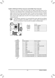
... 4 11 8 1) ATX_12V 2) ATX 3) CPU_FAN 4) SYS_FAN 5) CLR_CMOS 6) SATA2_0/1/2/3 7) BAT 8) F_PANEL 9) F_AUDIO 10) SPDIF_O 11) F_USB1/F_USB2 12) COM Read the following guidelines before turning on the motherboard. Hardware Installation - 22 - Unplug the power cord from the power outlet to prevent damage to the devices. • After installing the device and before connecting...
... 4 11 8 1) ATX_12V 2) ATX 3) CPU_FAN 4) SYS_FAN 5) CLR_CMOS 6) SATA2_0/1/2/3 7) BAT 8) F_PANEL 9) F_AUDIO 10) SPDIF_O 11) F_USB1/F_USB2 12) COM Read the following guidelines before turning on the motherboard. Hardware Installation - 22 - Unplug the power cord from the power outlet to prevent damage to the devices. • After installing the device and before connecting...
Manual
Page 23
... enough stable power to all devices are properly installed. Hardware Installation If the 12V power connector is turned off and all the components on the motherboard. Connect the power supply cable to the CPU. 1/2) ATX_12V/ATX (2x2 12V Power Connector and 2x12 Main Power Connector) With the use of the power...
... enough stable power to all devices are properly installed. Hardware Installation If the 12V power connector is turned off and all the components on the motherboard. Connect the power supply cable to the CPU. 1/2) ATX_12V/ATX (2x2 12V Power Connector and 2x12 Main Power Connector) With the use of the power...
Manual
Page 24
...a jumper cap on the headers. 5) CLR_CMOS (Clearing CMOS Jumper) Use this jumper to the CPU or the system may cause damage to the motherboard. • After system restart, go to BIOS Setup to load factory defaults (select Load Optimized Defaults) or manually configure the BIOS settings (refer... jumper cap from the jumper. Failure to do so may hang. • These fan headers are not configuration jumper blocks. 3/4) CPU_FAN/SYS_FAN (Fan Headers) The motherboard has a 4-pin CPU fan header (CPU_FAN) and a 3-pin (SYS_FAN) system fan headers. Definition 1 GND 2 +12V 3 Sense • Be sure to ...
...a jumper cap on the headers. 5) CLR_CMOS (Clearing CMOS Jumper) Use this jumper to the CPU or the system may cause damage to the motherboard. • After system restart, go to BIOS Setup to load factory defaults (select Load Optimized Defaults) or manually configure the BIOS settings (refer... jumper cap from the jumper. Failure to do so may hang. • These fan headers are not configuration jumper blocks. 3/4) CPU_FAN/SYS_FAN (Fan Headers) The motherboard has a 4-pin CPU fan header (CPU_FAN) and a 3-pin (SYS_FAN) system fan headers. Definition 1 GND 2 +12V 3 Sense • Be sure to ...

Manual
Page 27
...; The front panel audio header supports HD audio by expansion cards) for digital audio output from your motherboard to the instructions on both of the motherboard header. If your chassis front panel audio module to work or even damage it. Incorrect connection between ...signals will make the device unable to this header. If you to use a S/PDIF digital audio cable for digital audio output from your motherboard to Chapter 5, "Configuring 2/4/5.1/7.1-Channel Audio." • Some chassis provide a front panel audio module that has different wire assignments, please contact ...
...; The front panel audio header supports HD audio by expansion cards) for digital audio output from your motherboard to the instructions on both of the motherboard header. If your chassis front panel audio module to work or even damage it. Incorrect connection between ...signals will make the device unable to this header. If you to use a S/PDIF digital audio cable for digital audio output from your motherboard to Chapter 5, "Configuring 2/4/5.1/7.1-Channel Audio." • Some chassis provide a front panel audio module that has different wire assignments, please contact ...


