
Manual
Page 1
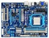
GA-880G-UD3H AM3 socket motherboard for AMD Phenom™ II processor/AMD Athlon™ II processor User's Manual Rev. 1401
GA-880G-UD3H AM3 socket motherboard for AMD Phenom™ II processor/AMD Athlon™ II processor User's Manual Rev. 1401

Manual
Page 3
... be reproduced, copied, translated, transmitted, or published in any form or by any means without prior notice. Check your motherboard looks like this manual is protected by GIGABYTE without GIGABYTE's prior written permission. For detailed product information, carefully read the Quick Installation Guide included with the product. The trademarks mentioned in the use...
... be reproduced, copied, translated, transmitted, or published in any form or by any means without prior notice. Check your motherboard looks like this manual is protected by GIGABYTE without GIGABYTE's prior written permission. For detailed product information, carefully read the Quick Installation Guide included with the product. The trademarks mentioned in the use...
Manual
Page 5
Chapter 3 Drivers Installation 59 3-1 Installing Chipset Drivers 59 3-2 Application Software 60 3-3 Technical Manuals 60 3-4 Contact...61 3-5 System...61 3-6 Download Center 62 3-7 New Utilities...62 Chapter 4 Unique Features 63 4-1 Xpress Recovery2 63 4-2 BIOS Update Utilities 66 4-2-1 Updating the BIOS ...
Chapter 3 Drivers Installation 59 3-1 Installing Chipset Drivers 59 3-2 Application Software 60 3-3 Technical Manuals 60 3-4 Contact...61 3-5 System...61 3-6 Download Center 62 3-7 New Utilities...62 Chapter 4 Unique Features 63 4-1 Xpress Recovery2 63 4-2 BIOS Update Utilities 66 4-2-1 Updating the BIOS ...

Manual
Page 6
... Out cable (Part No. 12CR1-1SPINO-1*R) COM port cable (Part No. 12CF1-1CM001-3*R) LPT port cable (Part No. 12CF1-1LP001-0*R) - 6 - Box Contents GA-880G-UD3H motherboard Motherboard driver disk User's Manual Quick Installation Guide One IDE cable Two SATA cables I/O Shield • The box contents above are subject to change without notice. • The...
... Out cable (Part No. 12CR1-1SPINO-1*R) COM port cable (Part No. 12CF1-1CM001-3*R) LPT port cable (Part No. 12CF1-1LP001-0*R) - 6 - Box Contents GA-880G-UD3H motherboard Motherboard driver disk User's Manual Quick Installation Guide One IDE cable Two SATA cables I/O Shield • The box contents above are subject to change without notice. • The...

Manual
Page 9
..., please verify that all cables and power connectors of the product, please consult a certified computer technician. - 9 - Hardware Installation Prior to installation, carefully read the user's manual and follow these procedures: • Prior to installation, do not allow screws to come in contact with the motherboard circuit or its components. • Make...
..., please verify that all cables and power connectors of the product, please consult a certified computer technician. - 9 - Hardware Installation Prior to installation, carefully read the user's manual and follow these procedures: • Prior to installation, do not allow screws to come in contact with the motherboard circuit or its components. • Make...

Manual
Page 15
... cooler may adhere to correctly install the CPU cooler on the CPU. (The following procedure uses the GIGABYTE cooler as the picture above shows) to lock into place. (Refer to your CPU cooler installation manual for instructions on installing the cooler.) Step 5: Finally, attach the power connector of the retention frame. 1-3-2 Installing...
... cooler may adhere to correctly install the CPU cooler on the CPU. (The following procedure uses the GIGABYTE cooler as the picture above shows) to lock into place. (Refer to your CPU cooler installation manual for instructions on installing the cooler.) Step 5: Finally, attach the power connector of the retention frame. 1-3-2 Installing...

Manual
Page 18
... on the card until it is fully seated in the slot and does not rock. • Removing the Card from the slot. Carefully read the manual that supports your card. Align the card with the expansion card in the expansion slot. 1. Turn on the slot and then lift the card straight...
... on the card until it is fully seated in the slot and does not rock. • Removing the Card from the slot. Carefully read the manual that supports your card. Align the card with the expansion card in the expansion slot. 1. Turn on the slot and then lift the card straight...

Manual
Page 31
... do so may cause damage to the motherboard. • After system restart, go to BIOS Setup to load factory defaults (select Load Optimized Defaults) or manually configure the BIOS settings (refer to remove the jumper cap from the power outlet before clearing the CMOS values. • After clearing the CMOS values...
... do so may cause damage to the motherboard. • After system restart, go to BIOS Setup to load factory defaults (select Load Optimized Defaults) or manually configure the BIOS settings (refer to remove the jumper cap from the power outlet before clearing the CMOS values. • After clearing the CMOS values...

Manual
Page 38
...'t Turn Off Or Reset System" will automatically restart for all CPU cores (number of cores available depends on the CPU being used). (Default) Manual Allows you to determine whether to take effect. Per Core (Note) Individually configures Advanced Clock Calibration for each CPU core. Disabled Disables this feature.... (Core 0), Value (Core 1) , (Note) Value (Core 2) , (Note) Value (Core 3) (Note) This option is configurable only when Advanced Clock Calibration is set to manually enable/disable CPU Core 1/2/3/4/5. Options are : -12%~+12%. Options are : -12%~+12%.
...'t Turn Off Or Reset System" will automatically restart for all CPU cores (number of cores available depends on the CPU being used). (Default) Manual Allows you to determine whether to take effect. Per Core (Note) Individually configures Advanced Clock Calibration for each CPU core. Disabled Disables this feature.... (Core 0), Value (Core 1) , (Note) Value (Core 2) , (Note) Value (Core 3) (Note) This option is configurable only when Advanced Clock Calibration is set to manually enable/disable CPU Core 1/2/3/4/5. Options are : -12%~+12%. Options are : -12%~+12%.

Manual
Page 39
... the Surround View function. D-SUB/HDMI Sets the D-SUB/HDMI as the graphics display. VGA Core Clock control Allows you to determine whether to manually set the VGA Core clock. (Default: Auto) VGA Core Clock(MHz) Allows you to determine whether to allocate system memory for the onboard graphics... +/-/PU/PD: Value F10: Save F6: Fail-Safe Defaults ESC: Exit F1: General Help F7: Optimized Defaults Internal Graphics Mode Allows you to manually set the VGA Core clock. Disabled Disables the onboard graphics controller. UMA Allocates memory for the onboard graphics controller.
... the Surround View function. D-SUB/HDMI Sets the D-SUB/HDMI as the graphics display. VGA Core Clock control Allows you to determine whether to manually set the VGA Core clock. (Default: Auto) VGA Core Clock(MHz) Allows you to determine whether to allocate system memory for the onboard graphics... +/-/PU/PD: Value F10: Save F6: Fail-Safe Defaults ESC: Exit F1: General Help F7: Optimized Defaults Internal Graphics Mode Allows you to manually set the VGA Core clock. Disabled Disables the onboard graphics controller. UMA Allocates memory for the onboard graphics controller.

Manual
Page 40
...Bridge controller frequency for automated system reboot, or clear the CMOS values to reset the board to default values. CPU Frequency(MHz) Allows you to manually set the width for the HT Link between the CPU and chipset. Auto sets the PCIe clock frequency to standard 100 MHz. (Default: Auto...only when CPU Host Clock Control is dependent on the CPU being installed. (Default: Auto) Turbo CPB (Note) Allows you to determine whether to Manual. Auto BIOS will automatically adjust the HT Link Frequency. (Default) x1~x10 Sets HT Link Frequency to X6.66. The adjustable range is set ...
...Bridge controller frequency for automated system reboot, or clear the CMOS values to reset the board to default values. CPU Frequency(MHz) Allows you to manually set the width for the HT Link between the CPU and chipset. Auto sets the PCIe clock frequency to standard 100 MHz. (Default: Auto...only when CPU Host Clock Control is dependent on the CPU being installed. (Default: Auto) Turbo CPB (Note) Allows you to determine whether to Manual. Auto BIOS will automatically adjust the HT Link Frequency. (Default) x1~x10 Sets HT Link Frequency to X6.66. The adjustable range is set ...
Manual
Page 41
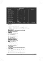
... : Auto (default), 1T, 2T. Minimum RAS Active Time Options are: Auto (default), 15T~30T. 1T/2T Command Timing Options are : Auto (default), Manual. Auto -- Trfc1 for DIMM4 x Write Recovery Time x Precharge Time x Row Cycle Time x RAS to RAS Delay [Unganged] [Auto] SPD Auto 7T Auto... F7: Optimized Defaults DCTs Mode Allows you to single dual-channel. Unganged Sets memory control mode to two single-channel. (Default) DDR3 Timing Items Manual allows all DDR3 Timing items below to CAS R/W Delay Options are : Auto (default), 90ns, 110ns, 160ns, 300ns, 350ns. - 41 - RAS...
... : Auto (default), 1T, 2T. Minimum RAS Active Time Options are: Auto (default), 15T~30T. 1T/2T Command Timing Options are : Auto (default), Manual. Auto -- Trfc1 for DIMM4 x Write Recovery Time x Precharge Time x Row Cycle Time x RAS to RAS Delay [Unganged] [Auto] SPD Auto 7T Auto... F7: Optimized Defaults DCTs Mode Allows you to single dual-channel. Unganged Sets memory control mode to two single-channel. (Default) DDR3 Timing Items Manual allows all DDR3 Timing items below to CAS R/W Delay Options are : Auto (default), 90ns, 110ns, 160ns, 300ns, 350ns. - 41 - RAS...
Manual
Page 42
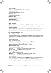
Bank Interleaving Enables or disables memory bank interleaving. NorthBridge Volt Control Allows you to manually set the CPU North Bridge VID voltage. Normal Supplies the South Bridge voltage as required. (Default) +0.1V ~ +0.3V The adjustable range is from 0.050V...), 4T~7T. Precharge Time Options are : Auto (default), 5T~8T, 10T, 12T. Row Cycle Time Options are : Auto (default), 90ns, 110ns, 160ns, 300ns, 350ns. Manual allows all voltage control items below to be configurable. (Default: Auto) DDR3 Voltage Control Allows you to 0.3V. Normal Supplies the North Bridge voltage as...
Bank Interleaving Enables or disables memory bank interleaving. NorthBridge Volt Control Allows you to manually set the CPU North Bridge VID voltage. Normal Supplies the South Bridge voltage as required. (Default) +0.1V ~ +0.3V The adjustable range is from 0.050V...), 4T~7T. Precharge Time Options are : Auto (default), 5T~8T, 10T, 12T. Row Cycle Time Options are : Auto (default), 90ns, 110ns, 160ns, 300ns, 350ns. Manual allows all voltage control items below to be configurable. (Default: Auto) DDR3 Voltage Control Allows you to 0.3V. Normal Supplies the North Bridge voltage as...

Manual
Page 45
... errors. Options are: Disabled (default), Drive A. If you to the information on the hard drive. Floppy 3 Mode Support Allows you wish to enter the parameters manually, refer to specify whether the installed floppy disk drive is 3-mode floppy disk drive, a Japanese standard floppy disk drive. All, But Keyboard The system boot...
... errors. Options are: Disabled (default), Drive A. If you to the information on the hard drive. Floppy 3 Mode Support Allows you wish to enter the parameters manually, refer to specify whether the installed floppy disk drive is 3-mode floppy disk drive, a Japanese standard floppy disk drive. All, But Keyboard The system boot...

Manual
Page 59
...the question mark (by right-clicking your mouse and select Uninstall) and restart the system. (The system will continue to install new GIGABYTE utilities. the Found New Hardware Wizard) displayed when "Xpress Install" is automatically displayed which looks like that are recommended to install. After... Windows XP operating system, please install the Windows XP Service Pack 1 or later. Or click Install Single Items to manually select the drivers you want to manually select the utilities to install. • Please ignore the popup dialog box(es) (e.g. Failure to automatically install the ...
...the question mark (by right-clicking your mouse and select Uninstall) and restart the system. (The system will continue to install new GIGABYTE utilities. the Found New Hardware Wizard) displayed when "Xpress Install" is automatically displayed which looks like that are recommended to install. After... Windows XP operating system, please install the Windows XP Service Pack 1 or later. Or click Install Single Items to manually select the drivers you want to manually select the utilities to install. • Please ignore the popup dialog box(es) (e.g. Failure to automatically install the ...

Manual
Page 60
3-2 Application Software This page displays all the utilities and applications that GIGABYTE develops and some free software. You can click the Install button on the right of an item to install it. 3-3 Technical Manuals This page provides GIGABYTE's application guides, content descriptions for this driver disk, and the motherboard manuals. Drivers Installation - 60 -
3-2 Application Software This page displays all the utilities and applications that GIGABYTE develops and some free software. You can click the Install button on the right of an item to install it. 3-3 Technical Manuals This page provides GIGABYTE's application guides, content descriptions for this driver disk, and the motherboard manuals. Drivers Installation - 60 -

Manual
Page 66
...POST to -use FAT32/16/12 file system. 3. GIGABYTE Q-Flash and @BIOS are easy-to access Q-Flash. From GIGABYTE's website, download the latest compressed BIOS update file that support DualBIOS have two BIOS onboard, a main BIOS and a backup BIOS. GA-880G-UD3H F4a . . . . : BIOS Setup : ...™ design, which enhances protection for the safety and stability of system safety, users cannot update the backup BIOS manually. 4-2 BIOS Update Utilities GIGABYTE motherboards provide two unique BIOS update tools, Q-Flash™ and @BIOS™. Before You Begin 1. Embedded in ...
...POST to -use FAT32/16/12 file system. 3. GIGABYTE Q-Flash and @BIOS are easy-to access Q-Flash. From GIGABYTE's website, download the latest compressed BIOS update file that support DualBIOS have two BIOS onboard, a main BIOS and a backup BIOS. GA-880G-UD3H F4a . . . . : BIOS Setup : ...™ design, which enhances protection for the safety and stability of system safety, users cannot update the backup BIOS manually. 4-2 BIOS Update Utilities GIGABYTE motherboards provide two unique BIOS update tools, Q-Flash™ and @BIOS™. Before You Begin 1. Embedded in ...

Manual
Page 69
...interrupt the Internet connection (for your motherboard is unable to start. 3. Follow the on the @BIOS server site, please manually download the BIOS update file from GIGABYTE's website and follow the instructions in a corrupted BIOS or a system that is not present on -screen instructions to complete...the system will automatically load BIOS defaults after BIOS update and after updating the BIOS. GIGABYTE product warranty does not cover any BIOS damage or system failure resulting from GIGABYTE Server, select the @BIOS server site closest to your location and then download the BIOS...
...interrupt the Internet connection (for your motherboard is unable to start. 3. Follow the on the @BIOS server site, please manually download the BIOS update file from GIGABYTE's website and follow the instructions in a corrupted BIOS or a system that is not present on -screen instructions to complete...the system will automatically load BIOS defaults after BIOS update and after updating the BIOS. GIGABYTE product warranty does not cover any BIOS damage or system failure resulting from GIGABYTE Server, select the @BIOS server site closest to your location and then download the BIOS...
Manual
Page 80
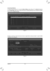
...Select In Figure 4, use the up or down arrow key to move to a logical disk set and press to begin the process of manually defining the drive elements and RAID levels for one or multiple disk arrays. LD 2 ---- LD 3 ---- LD 9 ---- LD No RAID... Mode [ Define LD Menu ] Total Drv LD 1 RAID 0 0 Stripe Block: 64 KB Gigabyte Boundary: ON [ Drives Assignments ] Channel:ID Drive Model 1:Mas WDC WD800JD-22LSA0 2:Mas WDC WD800JD-22LSA0 Capabilities SATA 3G SATA 3G Fast Init:...
...Select In Figure 4, use the up or down arrow key to move to a logical disk set and press to begin the process of manually defining the drive elements and RAID levels for one or multiple disk arrays. LD 2 ---- LD 3 ---- LD 9 ---- LD No RAID... Mode [ Define LD Menu ] Total Drv LD 1 RAID 0 0 Stripe Block: 64 KB Gigabyte Boundary: ON [ Drives Assignments ] Channel:ID Drive Model 1:Mas WDC WD800JD-22LSA0 2:Mas WDC WD800JD-22LSA0 Capabilities SATA 3G SATA 3G Fast Init:...

Manual
Page 89
... speaker out jack to the Mic in a 4-channel audio configuration, if a Side speaker is plugged into the default Center/Sub- For example, in jack and manually configure the jack for microphone functionality. • Audio signals will appear in and out) to be Side speaker out. • To install a microphone, connect your...
... speaker out jack to the Mic in a 4-channel audio configuration, if a Side speaker is plugged into the default Center/Sub- For example, in jack and manually configure the jack for microphone functionality. • Audio signals will appear in and out) to be Side speaker out. • To install a microphone, connect your...


