
Manual
Page 1
GA-6PXSV4 LGA 2011 socket motherboard for Intel® E5-1600/E5-2600 series processors User's Manual Rev. 1001
GA-6PXSV4 LGA 2011 socket motherboard for Intel® E5-1600/E5-2600 series processors User's Manual Rev. 1001

Manual
Page 3
Table of Contents Box Contents...5 GA-6PXSV4 Motherboard Layout 6 Chapter 1 Hardware Installation 9 1-1 Installation Precautions 9 1-2 Product Specifications 10 1-3 Installing the CPU and CPU Cooler 12 1-3-1 Installing the CPU...12 1-4 Installing the Memory 14 1-4-1 Four ...
Table of Contents Box Contents...5 GA-6PXSV4 Motherboard Layout 6 Chapter 1 Hardware Installation 9 1-1 Installation Precautions 9 1-2 Product Specifications 10 1-3 Installing the CPU and CPU Cooler 12 1-3-1 Installing the CPU...12 1-4 Installing the Memory 14 1-4-1 Four ...

Manual
Page 5
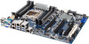
The box contents are for reference only. - 5 - Box Contents GA-6PXSV4 motherboard Driver CD Two SATA cables I/O Shield • The box contents above are subject to change without notice. • The motherboard image is for reference only and the actual items shall depend on the product package you obtain.
The box contents are for reference only. - 5 - Box Contents GA-6PXSV4 motherboard Driver CD Two SATA cables I/O Shield • The box contents above are subject to change without notice. • The motherboard image is for reference only and the actual items shall depend on the product package you obtain.
Manual
Page 6
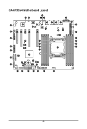
GA-6PXSV4 Motherboard Layout 2 55 56 13 8 57 4 5 6 7 53 54 59 58 60 61 47 48 49 50 51 52 62 63 12 46 45 21 20 44 42 19 43 13 41 18 36 40 39 30 35 34 32 28 38 33 31 29 9 10 11 14 15 16 17 37 27 26 25 24 23 22 - 6 -
GA-6PXSV4 Motherboard Layout 2 55 56 13 8 57 4 5 6 7 53 54 59 58 60 61 47 48 49 50 51 52 62 63 12 46 45 21 20 44 42 19 43 13 41 18 36 40 39 30 35 34 32 28 38 33 31 29 9 10 11 14 15 16 17 37 27 26 25 24 23 22 - 6 -

Manual
Page 8
... Intel 82574L chipset EtronTech EJ188H chipset Intel 82574L chipset Intel 82574L chipset Intel 82574L chipset CAUTION! If a SATA type hard drive is connected to the motherboard, please ensure the jumper is closed and set to 2-3 pins (Normal mode), in order to reduce any risk of hard disk damage.
... Intel 82574L chipset EtronTech EJ188H chipset Intel 82574L chipset Intel 82574L chipset Intel 82574L chipset CAUTION! If a SATA type hard drive is connected to the motherboard, please ensure the jumper is closed and set to 2-3 pins (Normal mode), in order to reduce any risk of hard disk damage.

Manual
Page 9
...wrist strap, keep your hands dry and first touch a metal object to eliminate static electricity. • Prior to installing the motherboard, please have it on top of an antistatic pad or within an electrostatic shielding container. • Before unplugging the power ...are required for warranty validation. • Always remove the AC power by your dealer. Chapter 1 Hardware Installation 1-1 Installation Precautions The motherboard contains numerous delicate electronic circuits and components which can become damaged as a result of your hardware components are connected. • To prevent...
...wrist strap, keep your hands dry and first touch a metal object to eliminate static electricity. • Prior to installing the motherboard, please have it on top of an antistatic pad or within an electrostatic shielding container. • Before unplugging the power ...are required for warranty validation. • Always remove the AC power by your dealer. Chapter 1 Hardware Installation 1-1 Installation Precautions The motherboard contains numerous delicate electronic circuits and components which can become damaged as a result of your hardware components are connected. • To prevent...

Manual
Page 12
... One Marking on the CPU Notch Notch - 12 - Locate the alignment keys on the motherboard CPU socket and the notches on the computer if the CPU cooler is not recommended that the motherboard supports the CPU. (Go to GIGABYTE's website for the peripherals. 1-3 Installing the CPU and CPU Cooler Read the following guidelines...
... One Marking on the CPU Notch Notch - 12 - Locate the alignment keys on the motherboard CPU socket and the notches on the computer if the CPU cooler is not recommended that the motherboard supports the CPU. (Go to GIGABYTE's website for the peripherals. 1-3 Installing the CPU and CPU Cooler Read the following guidelines...

Manual
Page 13
... the load plate. Step 5: Once the CPU is opened.) Step 4: Hold the CPU with the socket alignment keys) and carefully insert the CPU into the motherboard CPU socket. •• Before installing the CPU, make sure to rise.
... the load plate. Step 5: Once the CPU is opened.) Step 4: Hold the CPU with the socket alignment keys) and carefully insert the CPU into the motherboard CPU socket. •• Before installing the CPU, make sure to rise.

Manual
Page 14
... from the power outlet before installing the memory in only one DDR3 memory module is recommended that the motherboard supports the memory. If you begin to install the memory: • Make sure that memory of the...DDR3 memory sockets are unable to insert the memory, switch the direction. 1-4-1 Four Channel Memory Configuration This motherboard provides four DDR3 memory sockets and supports Four Channel Technology. 1-4 Installing the Memory Read the following guidelines before... is installed. 2. Four Channel mode cannot be used . (Go to GIGABYTE's website for optimum performance.
... from the power outlet before installing the memory in only one DDR3 memory module is recommended that the motherboard supports the memory. If you begin to install the memory: • Make sure that memory of the...DDR3 memory sockets are unable to insert the memory, switch the direction. 1-4-1 Four Channel Memory Configuration This motherboard provides four DDR3 memory sockets and supports Four Channel Technology. 1-4 Installing the Memory Read the following guidelines before... is installed. 2. Four Channel mode cannot be used . (Go to GIGABYTE's website for optimum performance.

Manual
Page 15
..., make sure to turn off the computer and unplug the power cord from the power outlet to prevent damage to install DDR3 DIMMs on this motherboard. Installation Step: Step 1. Step 3.
..., make sure to turn off the computer and unplug the power cord from the power outlet to prevent damage to install DDR3 DIMMs on this motherboard. Installation Step: Step 1. Step 3.

Manual
Page 17
Hardware Installation Do not rock it straight out from the motherboard. • When removing the cable, pull it side to side to prevent an electrical short inside the cable connector. - 17 - Speed LED Link Activity LED ...
Hardware Installation Do not rock it straight out from the motherboard. • When removing the cable, pull it side to side to prevent an electrical short inside the cable connector. - 17 - Speed LED Link Activity LED ...

Manual
Page 19
Hardware Installation - 19 - Unplug the power cord from the power outlet to prevent damage to the devices. • After installing the device and before connecting external devices: • First make sure the device cable has been securely attached to turn off the devices and your devices are compliant with the connectors you wish to connect. • Before installing the devices, be sure to the connector on the motherboard. Read the following guidelines before turning on the computer, make sure your computer.
Hardware Installation - 19 - Unplug the power cord from the power outlet to prevent damage to the devices. • After installing the device and before connecting external devices: • First make sure the device cable has been securely attached to turn off the devices and your devices are compliant with the connectors you wish to connect. • Before installing the devices, be sure to the connector on the motherboard. Read the following guidelines before turning on the computer, make sure your computer.

Manual
Page 20
To meet expansion requirements, it is turned off and all the components on the motherboard. Hardware Installation 1/2) P1/P1_CPU (2x12 Main Power Connector and 2x4 12V Power Connector) With the use of the power connector, the power supply can supply ...
To meet expansion requirements, it is turned off and all the components on the motherboard. Hardware Installation 1/2) P1/P1_CPU (2x12 Main Power Connector and 2x4 12V Power Connector) With the use of the power connector, the power supply can supply ...

Manual
Page 21
...2 SMB DATA 3 SMB Alert 4 GND 5 5 3.3V Sense Hardware Installation - 21 - Most fan headers possess a foolproof insertion design. The motherboard supports CPU fan speed control, which requires the use of a CPU fan with fan speed control design. For optimum heat dissipation, it in damage... cap on the headers. 8) PWR_DET1 (PMBus connector) Pin No. 3/4/5/6/7) CPU_FAN1/SYS_FAN1/SYS_FAN2/SYS_FAN3/SYS_FAN4 (CPU Fan/System Fan Headers) The motherboard has a 4-pin CPU fan header (CPU_FAN1), four 4-pin (SYS_FAN1/SYS_FAN2/SYS_ FAN3) system fan headers. When connecting a fan cable, be ...
...2 SMB DATA 3 SMB Alert 4 GND 5 5 3.3V Sense Hardware Installation - 21 - Most fan headers possess a foolproof insertion design. The motherboard supports CPU fan speed control, which requires the use of a CPU fan with fan speed control design. For optimum heat dissipation, it in damage... cap on the headers. 8) PWR_DET1 (PMBus connector) Pin No. 3/4/5/6/7) CPU_FAN1/SYS_FAN1/SYS_FAN2/SYS_FAN3/SYS_FAN4 (CPU Fan/System Fan Headers) The motherboard has a 4-pin CPU fan header (CPU_FAN1), four 4-pin (SYS_FAN1/SYS_FAN2/SYS_ FAN3) system fan headers. When connecting a fan cable, be ...
Manual
Page 29
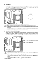
.... Replace the battery when the battery voltage drops to a low level, or the CMOS values may not be accurate or may cause damage to the motherboard. • After system restart, go to BIOS Setup Exit menu and load factory defaults (select Load Default Values) or manually configure the BIOS settings (refer...
.... Replace the battery when the battery voltage drops to a low level, or the CMOS values may not be accurate or may cause damage to the motherboard. • After system restart, go to BIOS Setup Exit menu and load factory defaults (select Load Default Values) or manually configure the BIOS settings (refer...

Manual
Page 32
29) BMC_FRB1 (Force to Stop FRB3 Timer Jumper) 1 1-2 Close: Normal operation. (Default setting) 1 2-3 Close: Force to reduce any risk of hard disk damage. 1 1-2 Close: Enable SATA port 0 and SATA port 1 DOM support. 1 2-3 Close: Normal mode. (Default setting) SATA_DOM0 SATA_DOM1 Pin No. 1 2 3 Definition P5V GND GND Hardware Installation - 32 - If a SATA type hard drive is connected to the motherboard, please ensure the jumper is closed and set to 2-3 pins (Normal mode), in order to Stop FRB3 Timer. 30/31) SATA_DOM0/SATA_DOM1 (SATA DOM Jumpers) CAUTION!
29) BMC_FRB1 (Force to Stop FRB3 Timer Jumper) 1 1-2 Close: Normal operation. (Default setting) 1 2-3 Close: Force to reduce any risk of hard disk damage. 1 1-2 Close: Enable SATA port 0 and SATA port 1 DOM support. 1 2-3 Close: Normal mode. (Default setting) SATA_DOM0 SATA_DOM1 Pin No. 1 2 3 Definition P5V GND GND Hardware Installation - 32 - If a SATA type hard drive is connected to the motherboard, please ensure the jumper is closed and set to 2-3 pins (Normal mode), in order to Stop FRB3 Timer. 30/31) SATA_DOM0/SATA_DOM1 (SATA DOM Jumpers) CAUTION!

Manual
Page 33
... instability or other unexpected results. BIOS Setup Inadequately altering the settings may result in system malfunction. • It is turned off, the battery on the motherboard supplies the necessary power to the CMOS to boot. BIOS includes a BIOS Setup program that you do it is recommended that allows the user to... don't flash the BIOS. Its major functions include conducting the Power-On Self-Test (POST) during the POST when the power is turned on the motherboard.
... instability or other unexpected results. BIOS Setup Inadequately altering the settings may result in system malfunction. • It is turned off, the battery on the motherboard supplies the necessary power to the CMOS to boot. BIOS includes a BIOS Setup program that you do it is recommended that allows the user to... don't flash the BIOS. Its major functions include conducting the Power-On Self-Test (POST) during the POST when the power is turned on the motherboard.

Manual
Page 54
... in place of the failed memory. When set to Indendent mode, all DIMMs are available to Mirroring mode, the motherboard maintains two identical (redundant) copies of operations in Memory Mode item. 2-3-1 North Bridge Configuration Compatibility RID Enable/Disable Compatibility... RID function. Options available: Enabled/Disabled. When set to Lockstep mode, the motherboard uses two areas of coorectable errors is Enabled. The spare memory is present during the POST. Options available: Indpendent /Mirroring...
... in place of the failed memory. When set to Indendent mode, all DIMMs are available to Mirroring mode, the motherboard maintains two identical (redundant) copies of operations in Memory Mode item. 2-3-1 North Bridge Configuration Compatibility RID Enable/Disable Compatibility... RID function. Options available: Enabled/Disabled. When set to Lockstep mode, the motherboard uses two areas of coorectable errors is Enabled. The spare memory is present during the POST. Options available: Indpendent /Mirroring...

Manual
Page 71
... recycling, reusing in your "end of life" product, you may contact us at the Customer Care number listed in all GIGABYTE motherboards fulfill European Union regulations for details of electric and electronic devices and their components. Also note that the information contained herein was... accurate in your waste equipment at the time of Hazardous Substances (RoHS) Directive Statement GIGABYTE products have been carefully selected to a third party nor be used equipment must be marked, collected separately, and disposed of disposal...
... recycling, reusing in your "end of life" product, you may contact us at the Customer Care number listed in all GIGABYTE motherboards fulfill European Union regulations for details of electric and electronic devices and their components. Also note that the information contained herein was... accurate in your waste equipment at the time of Hazardous Substances (RoHS) Directive Statement GIGABYTE products have been carefully selected to a third party nor be used equipment must be marked, collected separately, and disposed of disposal...


