

Instruction Manual
Page 2
...designed to provide reasonable protection against harmful interference when the equipment is subject to change without prior written consent from GE Security except where specifically permitted under US and international copyright law. Intended use or application of any liabilities, losses,...or omissions and specifically disclaims any of the contents of the FCC rules. This module contains a device with the limits for a Class A digital device, pursuant to radio communications. GE Security ("GE") assumes no responsibility for compliance could void the user's authority to comply with ...
...designed to provide reasonable protection against harmful interference when the equipment is subject to change without prior written consent from GE Security except where specifically permitted under US and international copyright law. Intended use or application of any liabilities, losses,...or omissions and specifically disclaims any of the contents of the FCC rules. This module contains a device with the limits for a Class A digital device, pursuant to radio communications. GE Security ("GE") assumes no responsibility for compliance could void the user's authority to comply with ...

Instruction Manual
Page 3
iii Contents Preface 1 Conventions used in this document 1 Safety terms and symbols 1 Product overview 2 Website activation of new and replacement modules 2 Enrolling the module 3 Module address 3 Installation 4 Mounting 4 Wiring 5 Module LEDs 6 Programming 8 Programming data 9 Location 0, programming the mode 10 Location 1, feature selection 10 Location 2, events to report to central station 11 Location 3, special events to...
iii Contents Preface 1 Conventions used in this document 1 Safety terms and symbols 1 Product overview 2 Website activation of new and replacement modules 2 Enrolling the module 3 Module address 3 Installation 4 Mounting 4 Wiring 5 Module LEDs 6 Programming 8 Programming data 9 Location 0, programming the mode 10 Location 1, feature selection 10 Location 2, events to report to central station 11 Location 3, special events to...

Instruction Manual
Page 5
.... Read these instructions and all required hardware installation. WARNING: Warnings identify conditions or practices that displays on accessing our online publication library. There is the GE NX-591E-GSM SMSXpress Module Installation Manual for instructions on the computer screen. The most current versions of this document effectively, you have a basic knowledge of the product and...
.... Read these instructions and all required hardware installation. WARNING: Warnings identify conditions or practices that displays on accessing our online publication library. There is the GE NX-591E-GSM SMSXpress Module Installation Manual for instructions on the computer screen. The most current versions of this document effectively, you have a basic knowledge of the product and...

Instruction Manual
Page 6
... conjunction with the panel communicator or other optional reporting modules. The module can activate and manage the module via our website address: www.gesecurity.com/GSM (Figure 1). 2 NX-591E-GSM SMSXpress Module Installation Manual Product overview The NX-591E-GSM is a microprocessor-controlled GSM interface module used to connect the NetworX series of new and replacement modules You can be reported, keeping airtime to a minimum...
... conjunction with the panel communicator or other optional reporting modules. The module can activate and manage the module via our website address: www.gesecurity.com/GSM (Figure 1). 2 NX-591E-GSM SMSXpress Module Installation Manual Product overview The NX-591E-GSM is a microprocessor-controlled GSM interface module used to connect the NetworX series of new and replacement modules You can be reported, keeping airtime to a minimum...
Instruction Manual
Page 7
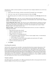
...NX control panel using the LCD keypad, the "Service Required" message will activate the GSM module (NX-591E-GSM). Multiple modules can be added from this screen. Enter the serial number of the module...module The NetworX control panels have the ability to configure the reporting for the module: • Select the unit you can be accepted during which time the service LED will automatically enroll all keypads, zone expanders, wireless... 1 that is replacing an existing cellemetry module. Edit unit settings. User codes will only activate a GSM module that was chosen (Alpha, E-mail...
...NX control panel using the LCD keypad, the "Service Required" message will activate the GSM module (NX-591E-GSM). Multiple modules can be added from this screen. Enter the serial number of the module...module The NetworX control panels have the ability to configure the reporting for the module: • Select the unit you can be accepted during which time the service LED will automatically enroll all keypads, zone expanders, wireless... 1 that is replacing an existing cellemetry module. Edit unit settings. User codes will only activate a GSM module that was chosen (Alpha, E-mail...

Instruction Manual
Page 8
...-moon protrusion fits into the smaller hole (from the inside of the can) to secure it in securely. 5. Slide the board in place. 4 NX-591E-GSM SMSXpress Module Installation Manual Installation To install the module you must either vertical or horizontal placement of the guide to mount and wire the ... mounted, screw it in the grooves of holes, a larger hole and a smaller hole. This allows for the screw. The end with the GSM module. In such cases, you will be seated. Mounting the board The halfmoon protrusion will need to tighten the screw. 3. Figure 2. Mounting Inside ...
...-moon protrusion fits into the smaller hole (from the inside of the can) to secure it in securely. 5. Slide the board in place. 4 NX-591E-GSM SMSXpress Module Installation Manual Installation To install the module you must either vertical or horizontal placement of the guide to mount and wire the ... mounted, screw it in the grooves of holes, a larger hole and a smaller hole. This allows for the screw. The end with the GSM module. In such cases, you will be seated. Mounting the board The halfmoon protrusion will need to tighten the screw. 3. Figure 2. Mounting Inside ...

Instruction Manual
Page 9
... the panel. 5 Wiring Table 1 shows the maximum wire run Length in feet 10 50 100 Wire gauge (connected to NX control panel or NX320E power supply) 20 18 16 Figure 3 shows the module wiring terminals and LEDs on page 24 for different wire gauges. Connect to Specifications on the board Figure 3. Table 1.
... the panel. 5 Wiring Table 1 shows the maximum wire run Length in feet 10 50 100 Wire gauge (connected to NX control panel or NX320E power supply) 20 18 16 Figure 3 shows the module wiring terminals and LEDs on page 24 for different wire gauges. Connect to Specifications on the board Figure 3. Table 1.

Instruction Manual
Page 10
... to DS6 LEDs flashing = Network failure. Flashing = Waiting for cellular service. Cellular service available. 6 NX-591E-GSM SMSXpress Module Installation Manual Module LEDs The module has 14 green LEDs along the back of the module as described in Table 3. Proper circuitry operation. Module LEDs LED DS1 DS3 DS4 DS5 DS6 XMIT POOR FAIR GOOD BEST SVC SVC2 RXD...
... to DS6 LEDs flashing = Network failure. Flashing = Waiting for cellular service. Cellular service available. 6 NX-591E-GSM SMSXpress Module Installation Manual Module LEDs The module has 14 green LEDs along the back of the module as described in Table 3. Proper circuitry operation. Module LEDs LED DS1 DS3 DS4 DS5 DS6 XMIT POOR FAIR GOOD BEST SVC SVC2 RXD...

Instruction Manual
Page 12
... until the last segment is waiting for a new programming location to be entered. Exit program mode Press Exit to exit this GSM module). You are repeated until the data is valid, the Service LED on the keypad will show the data for the first segment...of this programming level. Each time you may have entered previously. Press Exit a second time to 13) and press #. 8 NX-591E-GSM SMSXpress Module Installation Manual Programming You can select the module to program. The Ready LED will be displayed for a programming location to be entered. The keypad will flash.
... until the last segment is waiting for a new programming location to be entered. Exit program mode Press Exit to exit this GSM module). You are repeated until the data is valid, the Service LED on the keypad will show the data for the first segment...of this programming level. Each time you may have entered previously. Press Exit a second time to 13) and press #. 8 NX-591E-GSM SMSXpress Module Installation Manual Programming You can select the module to program. The Ready LED will be displayed for a programming location to be entered. The keypad will flash.

Instruction Manual
Page 14
... 7 Enable tamper switch Enabled Disabled 8 Disable SIA DCS area modifier3 Disabled Enabled 1. Factory default for future use of this module. Weekly test will be programmed for AutoSID. Note: If manually entering an SID, use . Segment 2 options Options Description ... time this option is 0-0-0-0-0 for the functioning of area (partition) modifiers. Factory default is programmed. 3. 10 NX-591E-GSM SMSXpress Module Installation Manual Location 0, programming the mode This location has five numeric data segments. Table 5 describes the options Table 5. Table...
... 7 Enable tamper switch Enabled Disabled 8 Disable SIA DCS area modifier3 Disabled Enabled 1. Factory default for future use of this module. Weekly test will be programmed for AutoSID. Note: If manually entering an SID, use . Segment 2 options Options Description ... time this option is 0-0-0-0-0 for the functioning of area (partition) modifiers. Factory default is programmed. 3. 10 NX-591E-GSM SMSXpress Module Installation Manual Location 0, programming the mode This location has five numeric data segments. Table 5 describes the options Table 5. Table...

Instruction Manual
Page 16
... report found in segments 1 through 16. Location 5 options Segment 1 2 Description Alarm restores Telephone fault Segment 3 4 Description Start download Fail to e-mail Phone fault detected. 12 NX-591E-GSM SMSXpress Module Installation Manual Location 4, events to report to function. Location 4 options Segment 1 2 3 4 5 6 7 8 Description Alarms Open/close Bypass Zone trouble Power trouble (AC failure or low...
... report found in segments 1 through 16. Location 5 options Segment 1 2 Description Alarm restores Telephone fault Segment 3 4 Description Start download Fail to e-mail Phone fault detected. 12 NX-591E-GSM SMSXpress Module Installation Manual Location 4, events to report to function. Location 4 options Segment 1 2 3 4 5 6 7 8 Description Alarms Open/close Bypass Zone trouble Power trouble (AC failure or low...

Instruction Manual
Page 18
... central station. Table 13. Location 9, special events to report to communicate, data lost Sensor low battery Expander trouble Failure to that particular partition number. 14 NX-591E-GSM SMSXpress Module Installation Manual Location 8, events to report to the central station. Table 14. Factory default is good. Note: Reporting must be enabled in segments 1 through...
... central station. Table 13. Location 9, special events to report to communicate, data lost Sensor low battery Expander trouble Failure to that particular partition number. 14 NX-591E-GSM SMSXpress Module Installation Manual Location 8, events to report to the central station. Table 14. Factory default is good. Note: Reporting must be enabled in segments 1 through...

Instruction Manual
Page 20
... Test reports Program, download, and log full Segment 9 10 11 12 13 14 15 16 Description Tampers Short circuit and ground fault Sensor lost 16 NX-591E-GSM SMSXpress Module Installation Manual Location 12, events to report to a pager. This location selects the partitions to include when reporting special events to pager Phone line...
... Test reports Program, download, and log full Segment 9 10 11 12 13 14 15 16 Description Tampers Short circuit and ground fault Sensor lost 16 NX-591E-GSM SMSXpress Module Installation Manual Location 12, events to report to a pager. This location selects the partitions to include when reporting special events to pager Phone line...

Instruction Manual
Page 22
... restores 2 Telephone fault 3 Start download 4 Fail to communicate, data lost 12 Sensor low battery 13 Expander trouble 14 Fail to 8 Reserved for future use . 18 NX-591E-GSM SMSXpress Module Installation Manual Location 2, Reporting events to central station (Phone line fault detected) Table 21.
... restores 2 Telephone fault 3 Start download 4 Fail to communicate, data lost 12 Sensor low battery 13 Expander trouble 14 Fail to 8 Reserved for future use . 18 NX-591E-GSM SMSXpress Module Installation Manual Location 2, Reporting events to central station (Phone line fault detected) Table 21.
Instruction Manual
Page 24
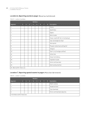
... restores 2 Telephone fault 3 Start download 4 Fail to communicate, data lost 12 Sensor low battery 13 Expander trouble 14 Fail to 8 Reserved for future use . 20 NX-591E-GSM SMSXpress Module Installation Manual Location 6, Reporting events to pager (Phone line fault detected) Table 25. Location 6 worksheet Partition Segment 1 2 3 4 5 6 7 8 Description 1 Alarms 2 Open/close 3 Bypass 4 Zone trouble...
... restores 2 Telephone fault 3 Start download 4 Fail to communicate, data lost 12 Sensor low battery 13 Expander trouble 14 Fail to 8 Reserved for future use . 20 NX-591E-GSM SMSXpress Module Installation Manual Location 6, Reporting events to pager (Phone line fault detected) Table 25. Location 6 worksheet Partition Segment 1 2 3 4 5 6 7 8 Description 1 Alarms 2 Open/close 3 Bypass 4 Zone trouble...

Instruction Manual
Page 26
Location 11, Reporting special events to e-mail (Phone line is good) Table 29. 22 NX-591E-GSM SMSXpress Module Installation Manual Location 10, Reporting events to e-mail (Phone line is good) Table 28. Location 11 worksheet Partition Segment 1 2 3 4 5 6 7 8 Description 1 Alarm restores 2 Telephone fault 3 Start ...
Location 11, Reporting special events to e-mail (Phone line is good) Table 29. 22 NX-591E-GSM SMSXpress Module Installation Manual Location 10, Reporting events to e-mail (Phone line is good) Table 28. Location 11 worksheet Partition Segment 1 2 3 4 5 6 7 8 Description 1 Alarm restores 2 Telephone fault 3 Start ...
Instruction Manual
Page 28
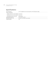
Standby with service LEDs disabled 70 mA max. Transmission burst ( 24 NX-591E-GSM SMSXpress Module Installation Manual Specifications Operating power Power consumption 12 VDC supplied from NX control panel or NX-320E power supply Standby with service LEDs enabled 90 mA max.
Standby with service LEDs disabled 70 mA max. Transmission burst ( 24 NX-591E-GSM SMSXpress Module Installation Manual Specifications Operating power Power consumption 12 VDC supplied from NX control panel or NX-320E power supply Standby with service LEDs enabled 90 mA max.

Instruction Manual
Page 31
27 Index A address ...3 C conventions 1 E enrollment 3 exit mode 8 F factory default 8 I installation 4 L LED ...5, 6 location programming 8 M module address 3 mounting 4 P preface ...1 product overview 2 program mode 8 programming 8 programming locations location 0 10 location 1 10 location 10 15 location 11 15 location 12 16 location 13 ...
27 Index A address ...3 C conventions 1 E enrollment 3 exit mode 8 F factory default 8 I installation 4 L LED ...5, 6 location programming 8 M module address 3 mounting 4 P preface ...1 product overview 2 program mode 8 programming 8 programming locations location 0 10 location 1 10 location 10 15 location 11 15 location 12 16 location 13 ...
