Installation Guide
Page 4
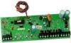
... (cascaded). When the power supply module is connected to the NetworX control panel, the maximum total wire run from the panel to the GE Security product catalog for residential applications only. It is a microprocessor controlled remote power supply module for all field wiring. Use a 16.5VAC 50VA / 120V, 60Hz hard-wired transformer (Part #T-0002) 4 NX-320E Power Supply UNDERWRITERS LABORATORIES INFORMATION...
... (cascaded). When the power supply module is connected to the NetworX control panel, the maximum total wire run from the panel to the GE Security product catalog for residential applications only. It is a microprocessor controlled remote power supply module for all field wiring. Use a 16.5VAC 50VA / 120V, 60Hz hard-wired transformer (Part #T-0002) 4 NX-320E Power Supply UNDERWRITERS LABORATORIES INFORMATION...

Installation Guide
Page 6
.... Connect as in diagram on the back of the NX-320E is off, this chart. To use this manual. Connect to the NX-320E board. NOTES: Refer to the power supply module. Connect as in diagram on the back of the power to a 16.5V 50 VA Class II UL approved... manual). If switch 4 is 2.5 Amps. ÊÊ for UL applications. AC Input. Shielded wire is the incoming data-signaling terminal to the control panel compatibility chart on page 7. The maximum total wire run from the NX-320E. Connect to the NX320E board. This terminal supplies power to the NetworX...
.... Connect as in diagram on the back of the NX-320E is off, this chart. To use this manual. Connect to the NX-320E board. NOTES: Refer to the power supply module. Connect as in diagram on the back of the power to a 16.5V 50 VA Class II UL approved... manual). If switch 4 is 2.5 Amps. ÊÊ for UL applications. AC Input. Shielded wire is the incoming data-signaling terminal to the control panel compatibility chart on page 7. The maximum total wire run from the NX-320E. Connect to the NX320E board. This terminal supplies power to the NetworX...

Installation Guide
Page 8
... to Compatibility chart on the back of this particular power supply. DS2 Flashes when data is used to be decided is the address of the NetworX control panel, and when the Program Mode is transmitted out from the NX-320E. Table IX:1 Address 84 85 86 87 88...to disable the Tamper feature ("On = enabled / "Off" = disabled). Dip Switch 4 is transmitted into the NX-320E. To enroll the modules enter the Program Mode of this manual). 8 NX-320E Power Supply Table XI:1 LED Description DS1 Flashes when data is exited, it is the address that must be supervised by ...
... to Compatibility chart on the back of this particular power supply. DS2 Flashes when data is used to be decided is the address of the NetworX control panel, and when the Program Mode is transmitted out from the NX-320E. Table IX:1 Address 84 85 86 87 88...to disable the Tamper feature ("On = enabled / "Off" = disabled). Dip Switch 4 is transmitted into the NX-320E. To enroll the modules enter the Program Mode of this manual). 8 NX-320E Power Supply Table XI:1 LED Description DS1 Flashes when data is exited, it is the address that must be supervised by ...