Installation Instructions
Page 1
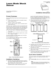
... types of the sensor. The sensor has two different detection modes: ❑ Gross Attack - A cover tamper provides additional security if an intruder tries to transmit an alarm signal. Mounting Options for mounting locations. Note On a vertical surface, the shock sensor element must always be... 6KRFN 6HQVRU ITI Part No. 60-886-95 60-886-11-95 Document Number: 466-1925 Rev. The circuit closes again when the vibration stops. Shock Sensor Wr… ‡vphyÃTˆ…shprÃH‚ˆ‡vt Shock Sensor Shock Sensor C‚…v“‚&#...
... types of the sensor. The sensor has two different detection modes: ❑ Gross Attack - A cover tamper provides additional security if an intruder tries to transmit an alarm signal. Mounting Options for mounting locations. Note On a vertical surface, the shock sensor element must always be... 6KRFN 6HQVRU ITI Part No. 60-886-95 60-886-11-95 Document Number: 466-1925 Rev. The circuit closes again when the vibration stops. Shock Sensor Wr… ‡vphyÃTˆ…shprÃH‚ˆ‡vt Shock Sensor Shock Sensor C‚…v“‚&#...
Installation Instructions
Page 2
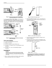
...secure the base to pry off the cover) ❑ Two #6 x 3/4" flathead screws for mounting the sensor (included) ❑ Two #6 x 5/8" screws for mounting the magnet (included) Installation Caution! You must disable the reed switch if you are better than parallel (see Figure 7). 4. Magnet alignment Important! Installation Shock Element ON 1 2 3 4 5 6 LOGO Shock... mounting orientation on the sensor case (see Figure 6). Arrows Magnet Figure 7. Position the shock element and press it . LOGO Shock Element ON 1 2 3 4 5 6 Mounting Hole (Located Under Shock Element) LOGO ON ...
...secure the base to pry off the cover) ❑ Two #6 x 3/4" flathead screws for mounting the sensor (included) ❑ Two #6 x 5/8" screws for mounting the magnet (included) Installation Caution! You must disable the reed switch if you are better than parallel (see Figure 7). 4. Magnet alignment Important! Installation Shock Element ON 1 2 3 4 5 6 LOGO Shock... mounting orientation on the sensor case (see Figure 6). Arrows Magnet Figure 7. Position the shock element and press it . LOGO Shock Element ON 1 2 3 4 5 6 Mounting Hole (Located Under Shock Element) LOGO ON ...


