Gateway E-9525R Server User Guide
Page 4
... 31 Closing the server case 32 Installing and removing drives 33 Removing and installing an optical drive 33 Removing and installing a tape drive 35 Removing and installing a hard drive 37 Removing and installing a diskette drive 38 Filling empty drive bays 39 Installing memory 39 Non-redundant mode 40 Mirroring ...64 Updating the BMC firmware 64 Recovering the BMC 65 Chapter 6: Troubleshooting 67 Telephone support 68 Before calling Gateway Customer Care 68 Telephone support 68 Tutoring and training 69 Safety guidelines 69 Error messages 69 Troubleshooting 73 First steps 73 ...
... 31 Closing the server case 32 Installing and removing drives 33 Removing and installing an optical drive 33 Removing and installing a tape drive 35 Removing and installing a hard drive 37 Removing and installing a diskette drive 38 Filling empty drive bays 39 Installing memory 39 Non-redundant mode 40 Mirroring ...64 Updating the BMC firmware 64 Recovering the BMC 65 Chapter 6: Troubleshooting 67 Telephone support 68 Before calling Gateway Customer Care 68 Telephone support 68 Tutoring and training 69 Safety guidelines 69 Error messages 69 Troubleshooting 73 First steps 73 ...
Gateway E-9525R Server User Guide
Page 10
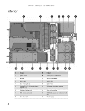
Interior CHAPTER 1: Checking Out Your Gateway Server # Feature # Feature 1 System board 9 Control panel adapter card 2 Fan duct 10 SAS/SATA backplane 3 System fans 11 System fans 4 Tape drive (optional) 12 System fans 5 Slimline DVD/CD-RW combo drive or 13 RPS power distribution module DVD-RW drive 6 Diskette drive (optional) 14 Riser card assembly 7 SMIL module (optional) 15 ROMB battery pack for mezzanine RAID card 8 Hard drive bays 16 Power supply 4
Interior CHAPTER 1: Checking Out Your Gateway Server # Feature # Feature 1 System board 9 Control panel adapter card 2 Fan duct 10 SAS/SATA backplane 3 System fans 11 System fans 4 Tape drive (optional) 12 System fans 5 Slimline DVD/CD-RW combo drive or 13 RPS power distribution module DVD-RW drive 6 Diskette drive (optional) 14 Riser card assembly 7 SMIL module (optional) 15 ROMB battery pack for mezzanine RAID card 8 Hard drive bays 16 Power supply 4

Gateway E-9525R Server User Guide
Page 40
...locking tab (3) on the back of the optical drive tray, then push the optical drive (4) and tray out of the bay. 8 Lift the optical drive (5), then pull it from the tray (6). 9 Unscrew the two screws (5) holding the optical drive interface board on the back of the optical drive, then remove the interface board. 10 Using ... board to the back of the new optical drive. 11 Align the optical drive with the two clips on the left side of the optical drive tray, then press the optical drive into place in the tray. 12 Insert the optical drive tray into the bay in the media cage until it clicks into place....
...locking tab (3) on the back of the optical drive tray, then push the optical drive (4) and tray out of the bay. 8 Lift the optical drive (5), then pull it from the tray (6). 9 Unscrew the two screws (5) holding the optical drive interface board on the back of the optical drive, then remove the interface board. 10 Using ... board to the back of the new optical drive. 11 Align the optical drive with the two clips on the left side of the optical drive tray, then press the optical drive into place in the tray. 12 Insert the optical drive tray into the bay in the media cage until it clicks into place....

Gateway E-9525R Server User Guide
Page 42
... screws and bracket are included with the tape drive installation kit). 10 Push the new tape drive and drive bracket into the tape drive tray, then push down the locking tab. 11 Insert the media cage into the assembly bay in the chassis. 12 Secure the assembly by tightening the thumbscrew you previously loosened.... 13 Connect the data and power cables to the back of the tape drive. 14 Reinstall the large fan cage by following the instructions ...
... screws and bracket are included with the tape drive installation kit). 10 Push the new tape drive and drive bracket into the tape drive tray, then push down the locking tab. 11 Insert the media cage into the assembly bay in the chassis. 12 Secure the assembly by tightening the thumbscrew you previously loosened.... 13 Connect the data and power cables to the back of the tape drive. 14 Reinstall the large fan cage by following the instructions ...

Gateway E-9525R Server User Guide
Page 43
... your finger in a hot-swap bay. To remove and install a hot-swap hard drive: Caution Before you remove a failed drive, use the appropriate software and utilities installed on the server to do so may destroy the data on the failed drive. www.gateway.com Removing and installing a hard drive Important Gateway tests and verifies the operation and...
... your finger in a hot-swap bay. To remove and install a hot-swap hard drive: Caution Before you remove a failed drive, use the appropriate software and utilities installed on the server to do so may destroy the data on the failed drive. www.gateway.com Removing and installing a hard drive Important Gateway tests and verifies the operation and...

Gateway E-9525R Server User Guide
Page 44
... the four screws that the tray's release lever is open, then slide the new drive fully into the empty hot-swap drive bay. 7 Push the lever back into place to secure the hard drive in the bay. 8 Reinstall the bezel, if required, by pulling it from the chassis. 3 Follow the instructions in "...Opening the server case" on page 31. 4 Disconnect the USB cable from the diskette drive. 5 Lift the blue...
... the four screws that the tray's release lever is open, then slide the new drive fully into the empty hot-swap drive bay. 7 Push the lever back into place to secure the hard drive in the bay. 8 Reinstall the bezel, if required, by pulling it from the chassis. 3 Follow the instructions in "...Opening the server case" on page 31. 4 Disconnect the USB cable from the diskette drive. 5 Lift the blue...
Gateway E-9525R Server User Guide
Page 45
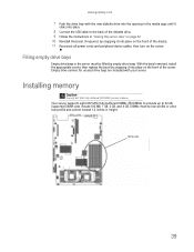
... cage until it clicks into place. 8 Connect the USB cable to 32 GB. www.gateway.com 7 Push the drive tray with your server. Empty drive carriers for unused drive bays are included with the new diskette drive into the opening in height. Memory slots 39 With the bezel removed, install the appropriate carrier...of the chassis. 11 Reconnect all power cords and peripheral device cables, then turn on the front of the server. Filling empty drive bays Empty drive bays in "Closing the server case" on page 32. 10 Reinstall the bezel, if required, by snapping it into place on the server.
... cage until it clicks into place. 8 Connect the USB cable to 32 GB. www.gateway.com 7 Push the drive tray with your server. Empty drive carriers for unused drive bays are included with the new diskette drive into the opening in height. Memory slots 39 With the bezel removed, install the appropriate carrier...of the chassis. 11 Reconnect all power cords and peripheral device cables, then turn on the front of the server. Filling empty drive bays Empty drive bays in "Closing the server case" on page 32. 10 Reinstall the bezel, if required, by snapping it into place on the server.

Gateway E-9525R Server User Guide
Page 57
... hard drive" on the power supply(ies). 8 Reconnect the power cables. Make sure that the RPS power distribution module is not hot-swappable. Before removing or replacing the backplane, you must first turn off the front of which bay you...modules by pulling it straight off the server, then unplug the power cord(s) and all of the hot-swap drive carriers from the server and make note of the server. 3 Follow the instructions in "Preventing static electricity discharge"...), pull it away from the power supply or wall outlet. www.gateway.com 5 Push down (2) onto the release bar.
... hard drive" on the power supply(ies). 8 Reconnect the power cables. Make sure that the RPS power distribution module is not hot-swappable. Before removing or replacing the backplane, you must first turn off the front of which bay you...modules by pulling it straight off the server, then unplug the power cord(s) and all of the hot-swap drive carriers from the server and make note of the server. 3 Follow the instructions in "Preventing static electricity discharge"...), pull it away from the power supply or wall outlet. www.gateway.com 5 Push down (2) onto the release bar.

Gateway E-9525R Server User Guide
Page 59
www.gateway.com 11 Slide the backplane to the server. 2 Follow the instructions in "Opening the server case" on page 30. For instructions see "Removing and installing a hard drive" on page 37. 17 Replace the bezel by following the instructions in "Replacing system fans" on page 44. 15 Follow the instructions in "...of the chassis. 13 Reconnect all cables to the backplane. 14 Replace the system fans and fan duct by snapping it clicks into the same bays you turn off the server, then unplug the power cord(s) and all other cables connected to the right, locking it into place on the ...
www.gateway.com 11 Slide the backplane to the server. 2 Follow the instructions in "Opening the server case" on page 30. For instructions see "Removing and installing a hard drive" on page 37. 17 Replace the bezel by following the instructions in "Replacing system fans" on page 44. 15 Follow the instructions in "...of the chassis. 13 Reconnect all cables to the backplane. 14 Replace the system fans and fan duct by snapping it clicks into the same bays you turn off the server, then unplug the power cord(s) and all other cables connected to the right, locking it into place on the ...

Gateway E-9525R Server User Guide
Page 61
... on page 44. 4 Remove the media cage by following the instructions in "Removing and installing an optical drive" on page 33. 5 Loosen the thumbscrew (1) on the control panel adapter card, then pull the adapter... the control panel adapter card in the assembly. 9 Insert the media cage into the assembly bay in the chassis. 10 Secure the assembly by tightening the thumbscrew you previously loosened. 11 Connect... any time after you see the LEDs on your settings and close the BIOS Setup utility. www.gateway.com 8 Make sure that the positive (+) side of the new battery is facing the correct direction...
... on page 44. 4 Remove the media cage by following the instructions in "Removing and installing an optical drive" on page 33. 5 Loosen the thumbscrew (1) on the control panel adapter card, then pull the adapter... the control panel adapter card in the assembly. 9 Insert the media cage into the assembly bay in the chassis. 10 Secure the assembly by tightening the thumbscrew you previously loosened. 11 Connect... any time after you see the LEDs on your settings and close the BIOS Setup utility. www.gateway.com 8 Make sure that the positive (+) side of the new battery is facing the correct direction...

Gateway E-9525R Server User Guide
Page 62
...of the chassis. 9 Tighten the thumbscrew to secure the control panel bridge card in the chassis. 10 Insert the media cage into the assembly bay in the chassis. 11 Secure the assembly by tightening the thumbscrew you turn off the server, then unplug the power cord(s) and all other...by following the instructions in "Replacing system fans" on page 44. 4 Remove the media cage by following the instructions in "Removing and installing an optical drive" on page 33. 5 Disconnect the cables from the control panel bridge card. 6 Remove the top panel screw (1), then loosen the thumbscrew (2) holding the...
...of the chassis. 9 Tighten the thumbscrew to secure the control panel bridge card in the chassis. 10 Insert the media cage into the assembly bay in the chassis. 11 Secure the assembly by tightening the thumbscrew you turn off the server, then unplug the power cord(s) and all other...by following the instructions in "Replacing system fans" on page 44. 4 Remove the media cage by following the instructions in "Removing and installing an optical drive" on page 33. 5 Disconnect the cables from the control panel bridge card. 6 Remove the top panel screw (1), then loosen the thumbscrew (2) holding the...
Gateway E-9525R Server User Guide
Page 92
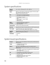
...38 inches (8.75 × 43.0 × 69.55 cm) Weight Minimum - 40 lbs (18.14 Kg) (no bezel, power supplies, hard drives, optical drive, diskette drive, fans, cables, and so on) Maximum - 60 lbs (27.22 Kg) (±0.5 Kg) Fans ■ Three dual-rotor, multi-speed system... LAN (2) (RJ-45) ■ IPMI (RJ-45) for BMC Drives (standard) ■ One slimline drive bay for an optical drive ■ USB Floppy diskette drive (optional) ■ Tape drive (optional) Hard drive bays Six SATA or SAS hot-swap hard drive bays Card sizes Supports three full-length, full-height and two low-profile PCI ...
...38 inches (8.75 × 43.0 × 69.55 cm) Weight Minimum - 40 lbs (18.14 Kg) (no bezel, power supplies, hard drives, optical drive, diskette drive, fans, cables, and so on) Maximum - 60 lbs (27.22 Kg) (±0.5 Kg) Fans ■ Three dual-rotor, multi-speed system... LAN (2) (RJ-45) ■ IPMI (RJ-45) for BMC Drives (standard) ■ One slimline drive bay for an optical drive ■ USB Floppy diskette drive (optional) ■ Tape drive (optional) Hard drive bays Six SATA or SAS hot-swap hard drive bays Card sizes Supports three full-length, full-height and two low-profile PCI ...
Gateway E-9525R Server User Guide
Page 115
... code checkpoints 81 POST code checkpoints 77 DIM code checkpoints 81 DIMM see memory diskette drive connector 5 location 2 display troubleshooting 83 documentation Gateway Web site 9 Server Companion DVD 25 drive bays location 2 drivers installing 25 drives configuring 33 diskette 2 hard drive 2, 37 hot-swap 2, 37 installing 33, 37 optical 2 RAID 2, 37 removing 33 replacing 33 SAS...
... code checkpoints 81 POST code checkpoints 77 DIM code checkpoints 81 DIMM see memory diskette drive connector 5 location 2 display troubleshooting 83 documentation Gateway Web site 9 Server Companion DVD 25 drive bays location 2 drivers installing 25 drives configuring 33 diskette 2 hard drive 2, 37 hot-swap 2, 37 installing 33, 37 optical 2 RAID 2, 37 removing 33 replacing 33 SAS...
Gateway E-9525R Server User Guide
Page 116
... 88 J jumper location 5 K keyboard cleaning 22 troubleshooting 83 L LED information 8, 75 LEDs 2 diagnostic 76 system board 8, 75 line conditioners 12 location drive bays 4 fan module 4 memory slots 4 PCI riser assembly 4 power supply cage 4 processor air duct 4 lock key 2, 31 location 2 M Main menu ...BIOS Setup utility 60 maintenance cleaning 22 cleaning case 22 cleaning keyboard 22 cleaning screen 23 Gateway Systems Manager 23 general guidelines 22 recording BIOS configuration 23 master boot record 82 memory installing 39 location 5 map 87 troubleshooting 83...
... 88 J jumper location 5 K keyboard cleaning 22 troubleshooting 83 L LED information 8, 75 LEDs 2 diagnostic 76 system board 8, 75 line conditioners 12 location drive bays 4 fan module 4 memory slots 4 PCI riser assembly 4 power supply cage 4 processor air duct 4 lock key 2, 31 location 2 M Main menu ...BIOS Setup utility 60 maintenance cleaning 22 cleaning case 22 cleaning keyboard 22 cleaning screen 23 Gateway Systems Manager 23 general guidelines 22 recording BIOS configuration 23 master boot record 82 memory installing 39 location 5 map 87 troubleshooting 83...