Canadian COM Radio Installation & Operation Limitations
Page 1
... Canada: GNS 480 (CNX80) Pilot's Guide GNS 480 (CNX80) Installation Manual SL30 NAV/COM Pilot's Guide SL30 NAV/COM Installation Manual SL40 VHF/COM Pilot's Guide SL40 VHF/COM Transceiver Installation Manual SL40 Mobile Supplemental User's Guide SL40 Mobile Installation Manual SL40 Base Station Supplemental User's Guide SL40 Base Station Installation Manual SL50 GPS Receiver and SL60 GPS Receiver/VHF/COM...
... Canada: GNS 480 (CNX80) Pilot's Guide GNS 480 (CNX80) Installation Manual SL30 NAV/COM Pilot's Guide SL30 NAV/COM Installation Manual SL40 VHF/COM Pilot's Guide SL40 VHF/COM Transceiver Installation Manual SL40 Mobile Supplemental User's Guide SL40 Mobile Installation Manual SL40 Base Station Supplemental User's Guide SL40 Base Station Installation Manual SL50 GPS Receiver and SL60 GPS Receiver/VHF/COM...
SL 40 User Guide
Page 3
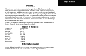
Once again, Garmin AT, Inc. The SL40 Installation Guide is unequaled in providing the features, level of performance, and reliability that helps you are built to last and to a new era of aviation .... -02 A Rev -02 B -02 Rev C -02 Rev D -02 Rev E -02 Rev F Ordering Information To receive additional copies of use by the aviation pilot. The SL40 is Garmin AT part #560-0956-xx. has set new standards in configurations to . Packaged in the future. Our products are the owner of the state-of...
Once again, Garmin AT, Inc. The SL40 Installation Guide is unequaled in providing the features, level of performance, and reliability that helps you are built to last and to a new era of aviation .... -02 A Rev -02 B -02 Rev C -02 Rev D -02 Rev E -02 Rev F Ordering Information To receive additional copies of use by the aviation pilot. The SL40 is Garmin AT part #560-0956-xx. has set new standards in configurations to . Packaged in the future. Our products are the owner of the state-of...
SL 40 User Guide
Page 4
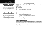
...home page. Look for assistance. The serial number is lost, stolen, or needs service. Be sure to keep your SL40 handy and connect to the Garmin Web site (www.garmin.com). Serial Number: NOTE: If you have any accessories) • Model number, part number with mod levels, ... space provided to the left. Also, be reached Monday through Friday, 7:00 AM to offer the following information about the installation: • Installation configuration (list of the unit. GARMIN International, Inc. 1200 East 151st Street Olathe, KS 66062-3426 USA Phone: FAX: US (913) 397-8200 US Toll...
...home page. Look for assistance. The serial number is lost, stolen, or needs service. Be sure to keep your SL40 handy and connect to the Garmin Web site (www.garmin.com). Serial Number: NOTE: If you have any accessories) • Model number, part number with mod levels, ... space provided to the left. Also, be reached Monday through Friday, 7:00 AM to offer the following information about the installation: • Installation configuration (list of the unit. GARMIN International, Inc. 1200 East 151st Street Olathe, KS 66062-3426 USA Phone: FAX: US (913) 397-8200 US Toll...

SL 40 User Guide
Page 6
... RSS-102 while using the Com transmitter, the operating limitations below must be observed, unless an installation-specific evaluation has been performed according to the requirements of RSS-102. • The Com antenna shall be installed in a location more than 24 inches (62 cm) from any pilot or required crew member of... the aircraft. • The Com antenna shall be installed in a location more than 52 inches (132 cm) from any other occupant of the aircraft. • If any bystander is within 52 inches (132 cm) ...
... RSS-102 while using the Com transmitter, the operating limitations below must be observed, unless an installation-specific evaluation has been performed according to the requirements of RSS-102. • The Com antenna shall be installed in a location more than 24 inches (62 cm) from any pilot or required crew member of... the aircraft. • The Com antenna shall be installed in a location more than 52 inches (132 cm) from any other occupant of the aircraft. • If any bystander is within 52 inches (132 cm) ...
SL 40 User Guide
Page 8
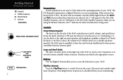
Standby Frequency m - If the avionics bus drops below 9 VDC, the SL40 will be installed to have power controlled from the avionics panel. Pull the knob out to view the features available within a function. Large (outer) and Small (inner) ...- An "s" will appear to switch between frequencies is lighted whenever you are using the Monitor function. Switching between the active (left side of your SL40. An LED will not transmit. Buttons Five backlighted buttons allow you are selected. Volume, Power, and Squelch Control Controls Power/Volume/Squelch The knob on...
Standby Frequency m - If the avionics bus drops below 9 VDC, the SL40 will be installed to have power controlled from the avionics panel. Pull the knob out to view the features available within a function. Large (outer) and Small (inner) ...- An "s" will appear to switch between frequencies is lighted whenever you are using the Monitor function. Switching between the active (left side of your SL40. An LED will not transmit. Buttons Five backlighted buttons allow you are selected. Volume, Power, and Squelch Control Controls Power/Volume/Squelch The knob on...
SL 40 User Guide
Page 10
...4 Detailed Operation This section introduces the basic operating details of the decimal point. Selecting Frequencies New frequencies are displayed to the right of the SL40 VHF Communications Transceiver. Standby frequency selection is between 000 and 975 kHz in 1 MHz steps. 2. Volume Turn the Power/Volume knob clockwise .... The kHz selection range is between 118 and 136 in 25 kHz steps. The SL40 may be installed to be powered from the avionics panel so the on the right side of the SL40 to change the values in 25 kHz increments. The MHz selection range is not inhibited...
...4 Detailed Operation This section introduces the basic operating details of the decimal point. Selecting Frequencies New frequencies are displayed to the right of the SL40 VHF Communications Transceiver. Standby frequency selection is between 000 and 975 kHz in 1 MHz steps. 2. Volume Turn the Power/Volume knob clockwise .... The kHz selection range is between 118 and 136 in 25 kHz steps. The SL40 may be installed to be powered from the avionics panel so the on the right side of the SL40 to change the values in 25 kHz increments. The MHz selection range is not inhibited...
SL 40 User Guide
Page 14
You can remove the ID for longer than 35 seconds, the SL40 will be reduced during intercom activity. When you select the Intercom function with the installed selector switch, the intercom function is detected, but the volume will return to the receive mode on . A small "I" is displayed above ... MEM to indicate the Intercom function is keyed for a frequency while retaining the frequency in User memory by setting all characters to the SL40, these headsets can be used as the active or standby frequency. The receive function will display until the transmit key is displayed only ...
You can remove the ID for longer than 35 seconds, the SL40 will be reduced during intercom activity. When you select the Intercom function with the installed selector switch, the intercom function is detected, but the volume will return to the receive mode on . A small "I" is displayed above ... MEM to indicate the Intercom function is keyed for a frequency while retaining the frequency in User memory by setting all characters to the SL40, these headsets can be used as the active or standby frequency. The receive function will display until the transmit key is displayed only ...


