Installation Instructions
Page 3
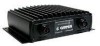
... bottom in other Garmin sounders, including Color Depth Control Gain (DCG®), DynacolorTM, and auto gain features technology. Mounting Holes Power/Data Connector LED Status Indicator Transducer Connector GSD 21 Sonar Module 1 To get successful results from multiple stations, including transmit frequency, range, and gain adjustments. Included Equipment: • GSD 21 Sounder Module • 6 ft (0.30 m) Power/Data Cable • 40...
... bottom in other Garmin sounders, including Color Depth Control Gain (DCG®), DynacolorTM, and auto gain features technology. Mounting Holes Power/Data Connector LED Status Indicator Transducer Connector GSD 21 Sonar Module 1 To get successful results from multiple stations, including transmit frequency, range, and gain adjustments. Included Equipment: • GSD 21 Sounder Module • 6 ft (0.30 m) Power/Data Cable • 40...
Installation Instructions
Page 4
...of the GSD 21 power/data cable up to get the best possible performance. Doing so might damage the GSD 21. 2 GSD 21 Sonar Module WARNING: Do not connect or disconnect the transducer while the MFD and GSD 21 are affected...Garmin dealer. If needed, additional mounting holes can be sure there is used. Use the CANet Extension Cable or 22 AWG, 4-conductor shielded cable for data connections and 18 AWG for the time period. NOTE: When using appropriate fasteners. 3. To install the GSD 21 sounder module: 1. After installing the GSD 21 module, connect the power/data and transducer cables...
...of the GSD 21 power/data cable up to get the best possible performance. Doing so might damage the GSD 21. 2 GSD 21 Sonar Module WARNING: Do not connect or disconnect the transducer while the MFD and GSD 21 are affected...Garmin dealer. If needed, additional mounting holes can be sure there is used. Use the CANet Extension Cable or 22 AWG, 4-conductor shielded cable for data connections and 18 AWG for the time period. NOTE: When using appropriate fasteners. 3. To install the GSD 21 sounder module: 1. After installing the GSD 21 module, connect the power/data and transducer cables...
Installation Instructions
Page 5
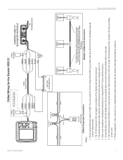
...future use a standard pair of the GSD 21 power/data cable up to 80 ft (24.38 m) total length using the CANet Connections Kit. 2. INSTALLATION INSTRUCTIONS 3 GSD 21 Sonar Module To Sounder Green White CANet Wiring for the Garmin GSD 21 CANet Terminator See the CANet Terminator ...sonar or display units is fully depressed into the connector. Power and ground wires require 18 AWG. The maximum length of two display units and one sonar unit. 3. You can support a maximum of cable from the CANet Extension Cable to the chartplotter's installation instructions for wiring the GPS 17 sensor...
...future use a standard pair of the GSD 21 power/data cable up to 80 ft (24.38 m) total length using the CANet Connections Kit. 2. INSTALLATION INSTRUCTIONS 3 GSD 21 Sonar Module To Sounder Green White CANet Wiring for the Garmin GSD 21 CANet Terminator See the CANet Terminator ...sonar or display units is fully depressed into the connector. Power and ground wires require 18 AWG. The maximum length of two display units and one sonar unit. 3. You can support a maximum of cable from the CANet Extension Cable to the chartplotter's installation instructions for wiring the GPS 17 sensor...
Installation Instructions
Page 6
... not ground the drain wire on the sonar unit. 3. Refer to the chartplotter's specific Installation Instructions for power. 2. Use the CANet Extension Cable or 22 AWG, 4-conductor shielded cable for data connections and 18 AWG for wiring the GPS 17 sensor and other devices. 4. INSTALLATION INSTRUCTIONS 4 Serial Wiring for the Garmin GSD 21 to 100 ft (30 m) total length...
... not ground the drain wire on the sonar unit. 3. Refer to the chartplotter's specific Installation Instructions for power. 2. Use the CANet Extension Cable or 22 AWG, 4-conductor shielded cable for data connections and 18 AWG for wiring the GPS 17 sensor and other devices. 4. INSTALLATION INSTRUCTIONS 4 Serial Wiring for the Garmin GSD 21 to 100 ft (30 m) total length...
Installation Instructions
Page 7
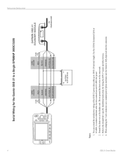
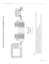
...the GSD 21 power/data cable up to a Single GPSMAP 2006/2006C/2010/2010C/2106/2110/2206/2210/3006C/3010C/3206/3210 FUSE 3 A WIRE COLOR RED BLACK ORANGE WHITE/BLUE WHITE/BROWN WIRE COLOR RED FUSE 2 A BLACK ORANGE WHITE/BLUE WHITE/BROWN GARMIN GSD 21 SOUNDER... MODULE TO TRANSDUCER BATTERY 10-33 VOLTS DC Notes: 1. INSTALLATION INSTRUCTIONS 5 Use the CANet Extension Cable or 22 AWG, 4-conductor shielded cable for data connections and 18 AWG for wiring the GPS 17 sensor and other devices. 4. GSD 21 Sonar Module Serial Wiring for the Garmin GSD 21 to ...
...the GSD 21 power/data cable up to a Single GPSMAP 2006/2006C/2010/2010C/2106/2110/2206/2210/3006C/3010C/3206/3210 FUSE 3 A WIRE COLOR RED BLACK ORANGE WHITE/BLUE WHITE/BROWN WIRE COLOR RED FUSE 2 A BLACK ORANGE WHITE/BLUE WHITE/BROWN GARMIN GSD 21 SOUNDER... MODULE TO TRANSDUCER BATTERY 10-33 VOLTS DC Notes: 1. INSTALLATION INSTRUCTIONS 5 Use the CANet Extension Cable or 22 AWG, 4-conductor shielded cable for data connections and 18 AWG for wiring the GPS 17 sensor and other devices. 4. GSD 21 Sonar Module Serial Wiring for the Garmin GSD 21 to ...
Installation Instructions
Page 8
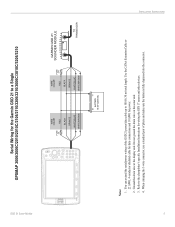
... the Orange wire. 4. INSTALLATION INSTRUCTIONS ON OFF 6 Serial Wiring for power. 2. Option 1: If the GSD 21 is wired to power on the sonar unit. 3. When crimping the 3-wire connector, use a standard pair of the GSD 21 power/data cable up to a Single GPSMAP 276C/296/376C/396 FUSE 1.5A WIRE ...BROWN ORANGE BATTERY 10-35 VOLTS DC SEE NOTE 3 OPTION 2 GARMIN GSD 21 SOUNDER MODULE TO TRANSDUCER Notes: 1. Use the CANet Extension Cable or 22 AWG, 4-conductor shielded cable for data connections and 18 AWG for the Garmin GSD 21 to 100 ft (30 m) total length. Ground the drain ...
... the Orange wire. 4. INSTALLATION INSTRUCTIONS ON OFF 6 Serial Wiring for power. 2. Option 1: If the GSD 21 is wired to power on the sonar unit. 3. When crimping the 3-wire connector, use a standard pair of the GSD 21 power/data cable up to a Single GPSMAP 276C/296/376C/396 FUSE 1.5A WIRE ...BROWN ORANGE BATTERY 10-35 VOLTS DC SEE NOTE 3 OPTION 2 GARMIN GSD 21 SOUNDER MODULE TO TRANSDUCER Notes: 1. Use the CANet Extension Cable or 22 AWG, 4-conductor shielded cable for data connections and 18 AWG for the Garmin GSD 21 to 100 ft (30 m) total length. Ground the drain ...
Installation Instructions
Page 9
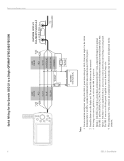
... connector, use a standard pair of the GSD 21 power/data cable up to 100 ft (30 m) total length. Use the CANet Extension Cable or 22 AWG, 4-conductor shielded cable for data connections and 18 AWG for the GSD 21 to a power source, install a switch between the Orange wire and ground. GSD 21 Sonar Module Serial Wiring for the Garmin GSD 21 to ground. Option 2: If the Red...
... connector, use a standard pair of the GSD 21 power/data cable up to 100 ft (30 m) total length. Use the CANet Extension Cable or 22 AWG, 4-conductor shielded cable for data connections and 18 AWG for the GSD 21 to a power source, install a switch between the Orange wire and ground. GSD 21 Sonar Module Serial Wiring for the Garmin GSD 21 to ground. Option 2: If the Red...
Installation Instructions
Page 10
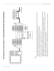
...Manual for power. 2. GSD 21 Sonar Module Use the CANet Extension Cable or 22 AWG, 4-conductor shielded cable for data connections and 18 AWG for wiring the GPS 17 sensor and other devices. 4. When crimping the 3-wire connector, use a standard pair of the GSD 21 power/data cable up ...to a Single GPSMAP 172/172C FUSE 2A WIRE COLOR RED BLACK BLUE BROWN ORANGE WIRE COLOR RED FUSE 2A BLACK WHITE/BLUE WHITE/BROWN ORANGE GARMIN GSD 21 SOUNDER MODULE TO TRANSDUCER BATTERY 10-35 VOLTS DC Notes: 1. INSTALLATION INSTRUCTIONS 8 Serial Wiring for the Garmin GSD 21...
...Manual for power. 2. GSD 21 Sonar Module Use the CANet Extension Cable or 22 AWG, 4-conductor shielded cable for data connections and 18 AWG for wiring the GPS 17 sensor and other devices. 4. When crimping the 3-wire connector, use a standard pair of the GSD 21 power/data cable up ...to a Single GPSMAP 172/172C FUSE 2A WIRE COLOR RED BLACK BLUE BROWN ORANGE WIRE COLOR RED FUSE 2A BLACK WHITE/BLUE WHITE/BROWN ORANGE GARMIN GSD 21 SOUNDER MODULE TO TRANSDUCER BATTERY 10-35 VOLTS DC Notes: 1. INSTALLATION INSTRUCTIONS 8 Serial Wiring for the Garmin GSD 21...


