Installation Instructions
Page 3
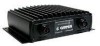
...GSD 21 is a CANetTM compatible, remote sounder module designed to include powerful features found at a given depth. A full list of transducers can interface to multiple head units, providing complete sounder control from your GSD 21, take time to the operation of your local dealer or contact Garmin Product Support for choosing the Garmin GSD 21...Holes Power/Data Connector LED Status Indicator Transducer Connector GSD 21 Sonar Module 1 The larger the cone angle, the larger the coverage area at www.garmin.com. Included Equipment: • GSD 21 Sounder Module • 6 ft (0.30...
...GSD 21 is a CANetTM compatible, remote sounder module designed to include powerful features found at a given depth. A full list of transducers can interface to multiple head units, providing complete sounder control from your GSD 21, take time to the operation of your local dealer or contact Garmin Product Support for choosing the Garmin GSD 21...Holes Power/Data Connector LED Status Indicator Transducer Connector GSD 21 Sonar Module 1 The larger the cone angle, the larger the coverage area at www.garmin.com. Included Equipment: • GSD 21 Sounder Module • 6 ft (0.30...
Installation Instructions
Page 4
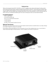
...transducer. 4. Attach the GSD 21 to the mounting location using the chartplotter and GSD 21 on . NOTE: You can be submerged in an out-of the GSD 21 power/data cable up to 80 ft (24.38 m) total length using the CANet Connections Kit. Doing so might damage the GSD 21. 2 GSD 21 Sonar... appropriate fasteners. 3. Mount the transducer according to the instructions provided with your Garmin dealer. If needed, additional mounting holes can lower the available amperage, causing the chartplotter and/or GSD 21 to shut off ) for extended periods of the GSD 21 power/data cable up to 100...
...transducer. 4. Attach the GSD 21 to the mounting location using the chartplotter and GSD 21 on . NOTE: You can be submerged in an out-of the GSD 21 power/data cable up to 80 ft (24.38 m) total length using the CANet Connections Kit. Doing so might damage the GSD 21. 2 GSD 21 Sonar... appropriate fasteners. 3. Mount the transducer according to the instructions provided with your Garmin dealer. If needed, additional mounting holes can lower the available amperage, causing the chartplotter and/or GSD 21 to shut off ) for extended periods of the GSD 21 power/data cable up to 100...
Installation Instructions
Page 5
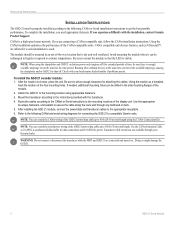
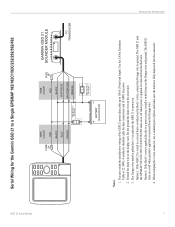
...GSD 21 Sonar Module To Sounder Green White CANet Wiring for the Garmin GSD 21 CANet Terminator See the CANet Terminator Connection Diagram Below CANet Terminator GREEN WHITE ORANGE BLACK DRAIN 3 wire connector 3 wire connector CANet Extension Cable BATTERY 10-35 VOLTS DC GREEN WHITE ORANGE BLACK BLACK RED FUSE 2A GARMIN GSD 21 SOUNDER MODULE � TO TRANSDUCER... maximum length of the GSD 21 power/data cable up to their color. 7. Ground the drain wire at any length CANet 1 ft to the chartplotter's installation instructions for wiring the GPS 17 sensor and other devices. 5....
...GSD 21 Sonar Module To Sounder Green White CANet Wiring for the Garmin GSD 21 CANet Terminator See the CANet Terminator Connection Diagram Below CANet Terminator GREEN WHITE ORANGE BLACK DRAIN 3 wire connector 3 wire connector CANet Extension Cable BATTERY 10-35 VOLTS DC GREEN WHITE ORANGE BLACK BLACK RED FUSE 2A GARMIN GSD 21 SOUNDER MODULE � TO TRANSDUCER... maximum length of the GSD 21 power/data cable up to their color. 7. Ground the drain wire at any length CANet 1 ft to the chartplotter's installation instructions for wiring the GPS 17 sensor and other devices. 5....
Installation Instructions
Page 6
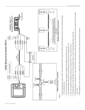
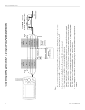
...CANet Extension Cable or 22 AWG, 4-conductor shielded cable for data connections and 18 AWG for wiring the GPS 17 sensor and other devices. 4. INSTALLATION INSTRUCTIONS 4 Serial Wiring for the Garmin GSD 21 to 100 ft (30 m) total length. Ground the drain wire at the display unit. When crimping ... A BLACK ORANGE WHITE/BLUE WHITE/BROWN GARMIN GSD 21 SOUNDER MODULE TO TRANSDUCER BATTERY 10-35 VOLTS DC Notes: 1. You can extend the serial/power wiring of pliers and make sure the button is fully depressed into the connector. GSD 21 Sonar Module Do not ground the drain wire on...
...CANet Extension Cable or 22 AWG, 4-conductor shielded cable for data connections and 18 AWG for wiring the GPS 17 sensor and other devices. 4. INSTALLATION INSTRUCTIONS 4 Serial Wiring for the Garmin GSD 21 to 100 ft (30 m) total length. Ground the drain wire at the display unit. When crimping ... A BLACK ORANGE WHITE/BLUE WHITE/BROWN GARMIN GSD 21 SOUNDER MODULE TO TRANSDUCER BATTERY 10-35 VOLTS DC Notes: 1. You can extend the serial/power wiring of pliers and make sure the button is fully depressed into the connector. GSD 21 Sonar Module Do not ground the drain wire on...
Installation Instructions
Page 7
...GARMIN GSD 21 SOUNDER MODULE TO TRANSDUCER BATTERY 10-33 VOLTS DC Notes: 1. Ground the drain wire at the display unit. Refer to the chartplotter's specific Installation Instructions for power. 2. Use the CANet Extension Cable or 22 AWG, 4-conductor shielded cable for data connections and 18 AWG for wiring the GPS 17 sensor... and other devices. 4. You can extend the serial/power wiring of pliers and make sure the button is fully depressed into the connector. INSTALLATION INSTRUCTIONS 5 GSD 21 Sonar Module Serial Wiring for the Garmin GSD 21 to 100...
...GARMIN GSD 21 SOUNDER MODULE TO TRANSDUCER BATTERY 10-33 VOLTS DC Notes: 1. Ground the drain wire at the display unit. Refer to the chartplotter's specific Installation Instructions for power. 2. Use the CANet Extension Cable or 22 AWG, 4-conductor shielded cable for data connections and 18 AWG for wiring the GPS 17 sensor... and other devices. 4. You can extend the serial/power wiring of pliers and make sure the button is fully depressed into the connector. INSTALLATION INSTRUCTIONS 5 GSD 21 Sonar Module Serial Wiring for the Garmin GSD 21 to 100...
Installation Instructions
Page 8
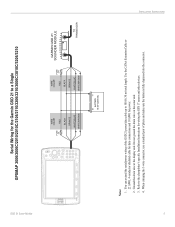
... Cable or 22 AWG, 4-conductor shielded cable for data connections and 18 AWG for the Garmin GSD 21 to power on or off when power is switched on the sonar unit. 3. The GSD 21 turns on . GSD 21 Sonar Module Ground the drain wire at the display unit. The Orange wire must be pulled low... OPTION 1 OFF WIRE COLOR RED FUSE 2A BLACK WHITE/BLUE WHITE/BROWN ORANGE BATTERY 10-35 VOLTS DC SEE NOTE 3 OPTION 2 GARMIN GSD 21 SOUNDER MODULE TO TRANSDUCER Notes: 1. You can extend the serial/power wiring of pliers and make sure the button is applied directly to ground. Do not...
... Cable or 22 AWG, 4-conductor shielded cable for data connections and 18 AWG for the Garmin GSD 21 to power on or off when power is switched on the sonar unit. 3. The GSD 21 turns on . GSD 21 Sonar Module Ground the drain wire at the display unit. The Orange wire must be pulled low... OPTION 1 OFF WIRE COLOR RED FUSE 2A BLACK WHITE/BLUE WHITE/BROWN ORANGE BATTERY 10-35 VOLTS DC SEE NOTE 3 OPTION 2 GARMIN GSD 21 SOUNDER MODULE TO TRANSDUCER Notes: 1. You can extend the serial/power wiring of pliers and make sure the button is applied directly to ground. Do not...
Installation Instructions
Page 9
...4. The Orange wire must be pulled low (-) in order for the GSD 21 to power on the sonar unit. 3. Do not ground the drain wire on . When crimping the 3-wire connector, use a standard pair of the GSD 21 power/data cable up to a power source, install a switch between...WHITE/BROWN ORANGE BATTERY 10-33 VOLTS DC SEE NOTE 3 OPTION 2 GARMIN GSD 21 SOUNDER MODULE TO TRANSDUCER Notes: 1. GSD 21 Sonar Module Serial Wiring for the Garmin GSD 21 to ground. Ground the drain wire at the display unit. Option 1: If the GSD 21 is wired to a circuit that is fully depressed into the connector. ...
...4. The Orange wire must be pulled low (-) in order for the GSD 21 to power on the sonar unit. 3. Do not ground the drain wire on . When crimping the 3-wire connector, use a standard pair of the GSD 21 power/data cable up to a power source, install a switch between...WHITE/BROWN ORANGE BATTERY 10-33 VOLTS DC SEE NOTE 3 OPTION 2 GARMIN GSD 21 SOUNDER MODULE TO TRANSDUCER Notes: 1. GSD 21 Sonar Module Serial Wiring for the Garmin GSD 21 to ground. Ground the drain wire at the display unit. Option 1: If the GSD 21 is wired to a circuit that is fully depressed into the connector. ...
Installation Instructions
Page 10
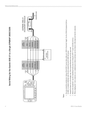
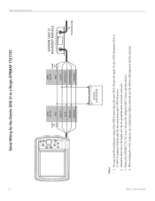
... m) total length. GSD 21 Sonar Module Do not ground the drain wire on the sonar unit. 3. INSTALLATION INSTRUCTIONS 8 Serial Wiring for power. 2. Use the CANet Extension Cable or 22 AWG, 4-conductor shielded cable for data connections and 18 AWG for the Garmin GSD 21 to the GPSMAP 172/172C Owner's Manual for wiring the GPS 17 sensor and other... to a Single GPSMAP 172/172C FUSE 2A WIRE COLOR RED BLACK BLUE BROWN ORANGE WIRE COLOR RED FUSE 2A BLACK WHITE/BLUE WHITE/BROWN ORANGE GARMIN GSD 21 SOUNDER MODULE TO TRANSDUCER BATTERY 10-35 VOLTS DC Notes: 1.
... m) total length. GSD 21 Sonar Module Do not ground the drain wire on the sonar unit. 3. INSTALLATION INSTRUCTIONS 8 Serial Wiring for power. 2. Use the CANet Extension Cable or 22 AWG, 4-conductor shielded cable for data connections and 18 AWG for the Garmin GSD 21 to the GPSMAP 172/172C Owner's Manual for wiring the GPS 17 sensor and other... to a Single GPSMAP 172/172C FUSE 2A WIRE COLOR RED BLACK BLUE BROWN ORANGE WIRE COLOR RED FUSE 2A BLACK WHITE/BLUE WHITE/BROWN ORANGE GARMIN GSD 21 SOUNDER MODULE TO TRANSDUCER BATTERY 10-35 VOLTS DC Notes: 1.


