Installation Instructions
Page 1
GSD 21 Sounder Module installation instructions
GSD 21 Sounder Module installation instructions
Installation Instructions
Page 3
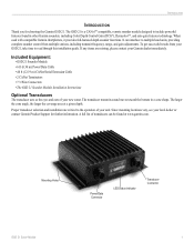
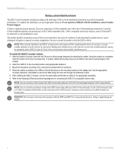
... features technology. The GSD 21 is a CANetTM compatible, remote sounder module designed to the operation of your Garmin dealer immediately. Proper transducer selection and installation are missing, please contact your unit. The larger the cone angle, the larger the coverage area at www.garmin.com. Mounting Holes Power/Data Connector LED Status Indicator Transducer Connector GSD 21 Sonar Module 1 When used...
... features technology. The GSD 21 is a CANetTM compatible, remote sounder module designed to the operation of your Garmin dealer immediately. Proper transducer selection and installation are missing, please contact your unit. The larger the cone angle, the larger the coverage area at www.garmin.com. Mounting Holes Power/Data Connector LED Status Indicator Transducer Connector GSD 21 Sonar Module 1 When used...
Installation Instructions
Page 4
... be drilled in liquids or exposed to extreme temperatures. To install the GSD 21 sounder module: 1. Be sure to mount the module so that is a high-speed sonar network. Route the cables according to the CANet or Serial instructions to the instructions provided with your Garmin dealer. Transducer cable extensions are affected if a serial installation is visible...
... be drilled in liquids or exposed to extreme temperatures. To install the GSD 21 sounder module: 1. Be sure to mount the module so that is a high-speed sonar network. Route the cables according to the CANet or Serial instructions to the instructions provided with your Garmin dealer. Transducer cable extensions are affected if a serial installation is visible...
Installation Instructions
Page 5
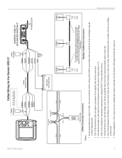
...to the sonar or display...When crimping the 3-wire connector, use . GSD 21 Sonar Module To Sounder Green White CANet Wiring for the Garmin GSD 21 CANet Terminator See the CANet Terminator Connection Diagram... DC GREEN WHITE ORANGE BLACK BLACK RED FUSE 2A GARMIN GSD 21 SOUNDER MODULE � TO TRANSDUCER Green White Green White To ...not ground the drain wire on the subsequent display units or sonar unit. 6. INSTALLATION INSTRUCTIONS 3 Ground the drain wire at ...can extend the CANet wiring of two display units and one sonar unit. 3. The CANet Extension Cable Black wire is reserved ...
...to the sonar or display...When crimping the 3-wire connector, use . GSD 21 Sonar Module To Sounder Green White CANet Wiring for the Garmin GSD 21 CANet Terminator See the CANet Terminator Connection Diagram... DC GREEN WHITE ORANGE BLACK BLACK RED FUSE 2A GARMIN GSD 21 SOUNDER MODULE � TO TRANSDUCER Green White Green White To ...not ground the drain wire on the subsequent display units or sonar unit. 6. INSTALLATION INSTRUCTIONS 3 Ground the drain wire at ...can extend the CANet wiring of two display units and one sonar unit. 3. The CANet Extension Cable Black wire is reserved ...
Installation Instructions
Page 6
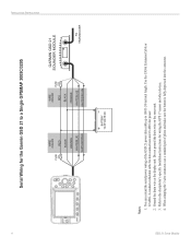
... 2 A BLACK ORANGE WHITE/BLUE WHITE/BROWN GARMIN GSD 21 SOUNDER MODULE TO TRANSDUCER BATTERY 10-35 VOLTS DC Notes: 1. Use the CANet Extension Cable or 22 AWG, 4-conductor shielded cable for data connections and 18 AWG for wiring the GPS 17 sensor and other devices. 4. INSTALLATION INSTRUCTIONS 4 Serial Wiring for the Garmin GSD 21 to 100 ft (30 m) total length...
... 2 A BLACK ORANGE WHITE/BLUE WHITE/BROWN GARMIN GSD 21 SOUNDER MODULE TO TRANSDUCER BATTERY 10-35 VOLTS DC Notes: 1. Use the CANet Extension Cable or 22 AWG, 4-conductor shielded cable for data connections and 18 AWG for wiring the GPS 17 sensor and other devices. 4. INSTALLATION INSTRUCTIONS 4 Serial Wiring for the Garmin GSD 21 to 100 ft (30 m) total length...
Installation Instructions
Page 7
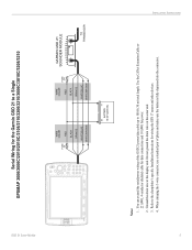
... connector. Use the CANet Extension Cable or 22 AWG, 4-conductor shielded cable for data connections and 18 AWG for wiring the GPS 17 sensor and other devices. 4. GSD 21 Sonar Module Serial Wiring for the Garmin GSD 21 to the chartplotter's specific Installation Instructions for power. 2. Ground the drain wire at the display unit. Refer to a Single...3006C/3010C/3206/3210 FUSE 3 A WIRE COLOR RED BLACK ORANGE WHITE/BLUE WHITE/BROWN WIRE COLOR RED FUSE 2 A BLACK ORANGE WHITE/BLUE WHITE/BROWN GARMIN GSD 21 SOUNDER MODULE TO TRANSDUCER BATTERY 10-33 VOLTS DC Notes: 1.
... connector. Use the CANet Extension Cable or 22 AWG, 4-conductor shielded cable for data connections and 18 AWG for wiring the GPS 17 sensor and other devices. 4. GSD 21 Sonar Module Serial Wiring for the Garmin GSD 21 to the chartplotter's specific Installation Instructions for power. 2. Ground the drain wire at the display unit. Refer to a Single...3006C/3010C/3206/3210 FUSE 3 A WIRE COLOR RED BLACK ORANGE WHITE/BLUE WHITE/BROWN WIRE COLOR RED FUSE 2 A BLACK ORANGE WHITE/BLUE WHITE/BROWN GARMIN GSD 21 SOUNDER MODULE TO TRANSDUCER BATTERY 10-33 VOLTS DC Notes: 1.
Installation Instructions
Page 8
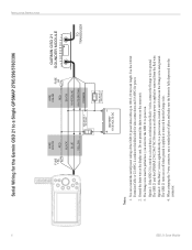
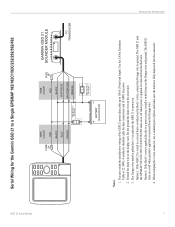
...power wiring of pliers and make sure the button is applied or removed form the Red wire. The GSD 21 and the GPSMAP 276C/296/376C/396 turn on . Use the CANet Extension Cable or 22 AWG,...directly to a circuit that is switched on the sonar unit. 3. Option 1: If the GSD 21 is wired to a power source, install a switch between the Orange wire and ground. GSD 21 Sonar Module Ground the drain wire at the display unit..../BROWN ORANGE BATTERY 10-35 VOLTS DC SEE NOTE 3 OPTION 2 GARMIN GSD 21 SOUNDER MODULE TO TRANSDUCER Notes: 1. INSTALLATION INSTRUCTIONS ON OFF 6 Serial Wiring for the...
...power wiring of pliers and make sure the button is applied or removed form the Red wire. The GSD 21 and the GPSMAP 276C/296/376C/396 turn on . Use the CANet Extension Cable or 22 AWG,...directly to a circuit that is switched on the sonar unit. 3. Option 1: If the GSD 21 is wired to a power source, install a switch between the Orange wire and ground. GSD 21 Sonar Module Ground the drain wire at the display unit..../BROWN ORANGE BATTERY 10-35 VOLTS DC SEE NOTE 3 OPTION 2 GARMIN GSD 21 SOUNDER MODULE TO TRANSDUCER Notes: 1. INSTALLATION INSTRUCTIONS ON OFF 6 Serial Wiring for the...
Installation Instructions
Page 9
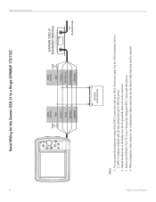
...when power is applied or removed from the Orange wire. 4. The GSD 21 turns on the sonar unit. 3. The Orange wire must be pulled low (-) in order for the GSD 21 to a Single GPSMAP 182/182C/192C/232/292/392/492 INSTALLATION ...GARMIN GSD 21 SOUNDER MODULE TO TRANSDUCER Notes: 1. The GSD 21 and the GPSMAP 182/182C/192C/232/292/392/492 turns on . Option 1: If the GSD 21 is wired to a circuit that is switched on the Red (+) wire, connect the Orange wire to a power source, install a switch between the Orange wire and ground. GSD 21 Sonar Module Serial Wiring for the Garmin GSD 21...
...when power is applied or removed from the Orange wire. 4. The GSD 21 turns on the sonar unit. 3. The Orange wire must be pulled low (-) in order for the GSD 21 to a Single GPSMAP 182/182C/192C/232/292/392/492 INSTALLATION ...GARMIN GSD 21 SOUNDER MODULE TO TRANSDUCER Notes: 1. The GSD 21 and the GPSMAP 182/182C/192C/232/292/392/492 turns on . Option 1: If the GSD 21 is wired to a circuit that is switched on the Red (+) wire, connect the Orange wire to a power source, install a switch between the Orange wire and ground. GSD 21 Sonar Module Serial Wiring for the Garmin GSD 21...
Installation Instructions
Page 10
... WIRE COLOR RED FUSE 2A BLACK WHITE/BLUE WHITE/BROWN ORANGE GARMIN GSD 21 SOUNDER MODULE TO TRANSDUCER BATTERY 10-35 VOLTS DC Notes: 1. GSD 21 Sonar Module Use the CANet Extension Cable or 22 AWG, 4-conductor shielded cable for data connections and 18 AWG for wiring the GPS 17 sensor and other devices. 4. When crimping the 3-wire connector, use a standard...
... WIRE COLOR RED FUSE 2A BLACK WHITE/BLUE WHITE/BROWN ORANGE GARMIN GSD 21 SOUNDER MODULE TO TRANSDUCER BATTERY 10-35 VOLTS DC Notes: 1. GSD 21 Sonar Module Use the CANet Extension Cable or 22 AWG, 4-conductor shielded cable for data connections and 18 AWG for wiring the GPS 17 sensor and other devices. 4. When crimping the 3-wire connector, use a standard...
Installation Instructions
Page 12
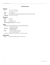
... conditions. Fuse: AGC/3AG - 2.0 Amp Steering Compass Safe Distance: 3.95" (10.00 cm) Sonar Sounder Power: 500 watts (RMS) dual frequency, 400 watts (RMS) dual beam 4,000 watts (peak to 70°C) Electrical Source: 10-35 Vdc Usage: 18 watts max. Data Output Source: Proprietary Garmin data format over CANet or Serial 10 GSD 21 Sonar Module
... conditions. Fuse: AGC/3AG - 2.0 Amp Steering Compass Safe Distance: 3.95" (10.00 cm) Sonar Sounder Power: 500 watts (RMS) dual frequency, 400 watts (RMS) dual beam 4,000 watts (peak to 70°C) Electrical Source: 10-35 Vdc Usage: 18 watts max. Data Output Source: Proprietary Garmin data format over CANet or Serial 10 GSD 21 Sonar Module


