
Installation Manual
Page 1
B GAD 43 Installation Manual 190-00899-00 May 2009 Rev.
B GAD 43 Installation Manual 190-00899-00 May 2009 Rev.
Installation Manual
Page 3
... or printed copy of this manual or revision must contain the complete text of this guide, please e-mail: Techpubs.Salem@garmin.com. or its subsidiaries All Rights Reserved Except as expressly provided herein, no part of this manual may be viewed and... to Section 1.2.1. Garmin International, Inc. 1200 E. 151st Street Olathe, KS 66062 USA Telephone: 913-397-8200 Aviation Dealer Technical Support Line (Toll Free): (888) 606 5482 http://www.garmin.com Garmin (Europe) Ltd. Added reference of Table 5-1 to a table (5-1). © Copyright 2009 Garmin Ltd. GAD 43 Installation Manual 190...
... or printed copy of this manual or revision must contain the complete text of this guide, please e-mail: Techpubs.Salem@garmin.com. or its subsidiaries All Rights Reserved Except as expressly provided herein, no part of this manual may be viewed and... to Section 1.2.1. Garmin International, Inc. 1200 E. 151st Street Olathe, KS 66062 USA Telephone: 913-397-8200 Aviation Dealer Technical Support Line (Toll Free): (888) 606 5482 http://www.garmin.com Garmin (Europe) Ltd. Added reference of Table 5-1 to a table (5-1). © Copyright 2009 Garmin Ltd. GAD 43 Installation Manual 190...

Installation Manual
Page 4
DOCUMENT PAGINATION Section Table of Contents Section 1 Section 2 Section 3 Section 4 Section 5 Section 6 Section 7 Section 8 Appendix A Appendix B Appendix C Page Range i through vi 1-1 through 1-8 2-1 through 2-2 3-1 through 3-8 4-1 through 4-8 5-1 through 5-4 6-1 through 6-2 7-1 through 7-2 8-1 through 8-2 A-1 through A-2 B-1 through B-4 C-1 through C-8 Page B Rev. B GAD 43 Installation Manual 190-00899-00
DOCUMENT PAGINATION Section Table of Contents Section 1 Section 2 Section 3 Section 4 Section 5 Section 6 Section 7 Section 8 Appendix A Appendix B Appendix C Page Range i through vi 1-1 through 1-8 2-1 through 2-2 3-1 through 3-8 4-1 through 4-8 5-1 through 5-4 6-1 through 6-2 7-1 through 7-2 8-1 through 8-2 A-1 through A-2 B-1 through B-4 C-1 through C-8 Page B Rev. B GAD 43 Installation Manual 190-00899-00
Installation Manual
Page 5
... to cause cancer, birth defects, or reproductive harm. WARNING This product, its packaging, and its components contain chemicals known to our web site at www.garmin.com/prop65/. The preceding statement is being provided in this manual. GAD 43 Installation Manual 190-00899-00 Page i Rev.
... to cause cancer, birth defects, or reproductive harm. WARNING This product, its packaging, and its components contain chemicals known to our web site at www.garmin.com/prop65/. The preceding statement is being provided in this manual. GAD 43 Installation Manual 190-00899-00 Page i Rev.

Installation Manual
Page 6
This Page Intentionally Left Blank Page ii Rev. B GAD 43 Installation Manual 190-00899-00
This Page Intentionally Left Blank Page ii Rev. B GAD 43 Installation Manual 190-00899-00
Installation Manual
Page 7
... 3.8 Continued Airworthiness ...3-7 4. B SYSTEM INTERCONNECTS...4-1 4.1 Pin Function List...4-1 4.1.1 P431 Connector...4-1 4.2 Functional Descriptions ...4-3 4.2.1 Power...4-3 4.2.2 Power Supply Outputs...4-3 4.2.3 Serial Data...4-3 4.2.4 Gyro Emulation Interfaces 4-4 4.2.5 Baro Correction Outputs ...4-6 4.2.6 Discretes...4-6 GAD 43 Installation Manual 190-00899-00 Page iii Rev. GENERAL DESCRIPTION...1-1 1.1 Introduction...1-1 1.2 Equipment Description ...1-2 1.2.1 System Interface Functions 1-2 1.3 Interface Summary...1-2 1.3.1 ARINC 429 Interface ...1-2 1.3.2 RS-232 Interface...
... 3.8 Continued Airworthiness ...3-7 4. B SYSTEM INTERCONNECTS...4-1 4.1 Pin Function List...4-1 4.1.1 P431 Connector...4-1 4.2 Functional Descriptions ...4-3 4.2.1 Power...4-3 4.2.2 Power Supply Outputs...4-3 4.2.3 Serial Data...4-3 4.2.4 Gyro Emulation Interfaces 4-4 4.2.5 Baro Correction Outputs ...4-6 4.2.6 Discretes...4-6 GAD 43 Installation Manual 190-00899-00 Page iii Rev. GENERAL DESCRIPTION...1-1 1.1 Introduction...1-1 1.2 Equipment Description ...1-2 1.2.1 System Interface Functions 1-2 1.3 Interface Summary...1-2 1.3.1 ARINC 429 Interface ...1-2 1.3.2 RS-232 Interface...
Installation Manual
Page 8
... Preparation ...3-4 Figure 3-3. Installation Accessories ...2-1 Table 3-1. GAD 43 Power Interconnect C-3 Figure C-2. SYSTEM CONFIGURATION AND CHECKOUT 5-1 5.1 Post Installation Power Check ...5-1 5.2 GAD 43 Software Loading ...5-1 5.3 Initial Configuration of GAD 43 2-2 Figure 3-1. GAD 43 WXR Stabilization Interconnect C-8 LIST OF TABLES Table 2-1. Shield Termination on Backshell Assembly 3-5 Figure B-1. B GAD 43 Installation Manual 190-00899-00 GAD 43 Unit View ...1-1 Figure 2-1. 4.2.7 Relays...4-7 5. GAD 43 Remote Mount Gyro Replacement Interconnect C-5 Figure C-4.
... Preparation ...3-4 Figure 3-3. Installation Accessories ...2-1 Table 3-1. GAD 43 Power Interconnect C-3 Figure C-2. SYSTEM CONFIGURATION AND CHECKOUT 5-1 5.1 Post Installation Power Check ...5-1 5.2 GAD 43 Software Loading ...5-1 5.3 Initial Configuration of GAD 43 2-2 Figure 3-1. GAD 43 WXR Stabilization Interconnect C-8 LIST OF TABLES Table 2-1. Shield Termination on Backshell Assembly 3-5 Figure B-1. B GAD 43 Installation Manual 190-00899-00 GAD 43 Unit View ...1-1 Figure 2-1. 4.2.7 Relays...4-7 5. GAD 43 Remote Mount Gyro Replacement Interconnect C-5 Figure C-4.
Installation Manual
Page 9
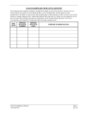
...current at www.garmin.com using their Garmin-provided user name and password. GAD 43 HARDWARE MOD LEVEL HISTORY The following table identifies hardware modification (Mod) Levels for the GAD 43. MOD LEVEL SERVICE BULLETIN NUMBER SERVICE BULLETIN DATE PURPOSE OF MODIFICATION GAD 43 Installation Manual ...190-00899-00 Page v Rev. B Authorized Garmin Sales and Service Centers are listed with the associated...
...current at www.garmin.com using their Garmin-provided user name and password. GAD 43 HARDWARE MOD LEVEL HISTORY The following table identifies hardware modification (Mod) Levels for the GAD 43. MOD LEVEL SERVICE BULLETIN NUMBER SERVICE BULLETIN DATE PURPOSE OF MODIFICATION GAD 43 Installation Manual ...190-00899-00 Page v Rev. B Authorized Garmin Sales and Service Centers are listed with the associated...

Installation Manual
Page 10
This page intentionally left blank Page vi Rev. B GAD 43 Installation Manual 190-00899-00
This page intentionally left blank Page vi Rev. B GAD 43 Installation Manual 190-00899-00
Installation Manual
Page 11
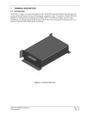
GENERAL DESCRIPTION 1.1 Introduction The GAD 43 Adapter is installed. Figure 1-1. B GAD 43 Unit View GAD 43 Installation Manual 190-00899-00 Page 1-1 Rev. 1. For attitude-based autopilots, the GAD 43 allows the existing ADI or attitude gyro to be removed when the G500/G600 system is an optional adapter for the G500/G600 Integrated Flight Decks that provides analog attitude information for use with third-party autopilot systems. It interfaces with the GDU 620 Display for configuration and alerting, and with the GRS 77 for attitude, heading, and yaw input information.
GENERAL DESCRIPTION 1.1 Introduction The GAD 43 Adapter is installed. Figure 1-1. B GAD 43 Unit View GAD 43 Installation Manual 190-00899-00 Page 1-1 Rev. 1. For attitude-based autopilots, the GAD 43 allows the existing ADI or attitude gyro to be removed when the G500/G600 system is an optional adapter for the G500/G600 Integrated Flight Decks that provides analog attitude information for use with third-party autopilot systems. It interfaces with the GDU 620 Display for configuration and alerting, and with the GRS 77 for attitude, heading, and yaw input information.
Installation Manual
Page 12
.... Various analog interfaces (including ARINC 407) are compatible with the gyros identified in the following sections. 1.3.3.1 Power Supply Outputs The GAD 43 can be configured to provide pitch and roll attitude (including valid relays), heading (including valid signal), yaw rate, and barometric correction... correction information emulates the analog output (pickoff) of +26 VDC, 26 VAC, and 5 VAC are provided for GAD 43 configuration and display of GAD 43 alerts. • Interfacing to autopilots that uses typical ARINC 429, and RS-232 communication interfaces. For the system to...
.... Various analog interfaces (including ARINC 407) are compatible with the gyros identified in the following sections. 1.3.3.1 Power Supply Outputs The GAD 43 can be configured to provide pitch and roll attitude (including valid relays), heading (including valid signal), yaw rate, and barometric correction... correction information emulates the analog output (pickoff) of +26 VDC, 26 VAC, and 5 VAC are provided for GAD 43 configuration and display of GAD 43 alerts. • Interfacing to autopilots that uses typical ARINC 429, and RS-232 communication interfaces. For the system to...
Installation Manual
Page 13
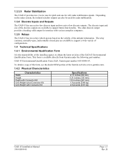
... discrete outputs are available to support a wide-variety of configurations. 1.4 Technical Specifications 1.4.1 Environmental Qualification Form It is available directly from Garmin under the following part number: GAD 43 Environmental Qualification Form, EQF, Garmin part number 005-00496-07. The other discrete output provides a heading valid output for interface with Connector Kit Specifications 2.11 inches...
... discrete outputs are available to support a wide-variety of configurations. 1.4 Technical Specifications 1.4.1 Environmental Qualification Form It is available directly from Garmin under the following part number: GAD 43 Environmental Qualification Form, EQF, Garmin part number 005-00496-07. The other discrete output provides a heading valid output for interface with Connector Kit Specifications 2.11 inches...

Installation Manual
Page 14
B GAD 43 Installation Manual 190-00899-00 Characteristics Operating Temperature Range Humidity Altitude Range Environmental Compliance Input Voltage Range Specifications -55°C to +70°C 240 Hours 65°C 95% 55,000 ft maximum RTCA/DO-160E 10 to 40 VDC 1.4.4 Power Consumption Ambient temperature above -15°C: 14 VDC 28 VDC Typical 0.41A 0.21A Maximum 0.72A 0.35A Page 1-4 Rev. For detailed specifications, see the Environmental Qualification Form. 1.4.3 General Specifications The table below contains general environmental specifications.
B GAD 43 Installation Manual 190-00899-00 Characteristics Operating Temperature Range Humidity Altitude Range Environmental Compliance Input Voltage Range Specifications -55°C to +70°C 240 Hours 65°C 95% 55,000 ft maximum RTCA/DO-160E 10 to 40 VDC 1.4.4 Power Consumption Ambient temperature above -15°C: 14 VDC 28 VDC Typical 0.41A 0.21A Maximum 0.72A 0.35A Page 1-4 Rev. For detailed specifications, see the Environmental Qualification Form. 1.4.3 General Specifications The table below contains general environmental specifications.
Installation Manual
Page 15
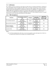
... GMN-00724. TSO articles must have separate approval for installation in the table above are for an incomplete system and requires the GAD 43 to be installed and checked out according to this article either on behalf of those installing this installation manual. B The article may... conditions are within a specific type or class of this article are minimum performance standards. The Appliance Project Identifier for the for the GAD 43 is the responsibility of this project will be installed only in compliance under and referred to by this number. 1.5.1 TSO Compliance Function...
... GMN-00724. TSO articles must have separate approval for installation in the table above are for an incomplete system and requires the GAD 43 to be installed and checked out according to this article either on behalf of those installing this installation manual. B The article may... conditions are within a specific type or class of this article are minimum performance standards. The Appliance Project Identifier for the for the GAD 43 is the responsibility of this project will be installed only in compliance under and referred to by this number. 1.5.1 TSO Compliance Function...
Installation Manual
Page 16
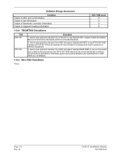
B GAD 43 Installation Manual 190-00899-00 Garmin was granted a deviation from SAE Aerospace Standard ...as the standard for Environmental Conditions and Test Procedures for Minimum Performance Standards and Environmental Standards. 2. Garmin was granted a deviation from SAE Aerospace Standard SAE 402A to use SAE AS 8001 instead of ... (performance and qualification test specifications in SAE 402A are not affected). 1.5.3 Non-TSO Functions None. Page 1-6 Rev. Garmin was granted a deviation from TSO-C4c to use RTCA DO-160E instead of magnetic heading information DO-178B Level A...
B GAD 43 Installation Manual 190-00899-00 Garmin was granted a deviation from SAE Aerospace Standard ...as the standard for Environmental Conditions and Test Procedures for Minimum Performance Standards and Environmental Standards. 2. Garmin was granted a deviation from SAE Aerospace Standard SAE 402A to use SAE AS 8001 instead of ... (performance and qualification test specifications in SAE 402A are not affected). 1.5.3 Non-TSO Functions None. Page 1-6 Rev. Garmin was granted a deviation from TSO-C4c to use RTCA DO-160E instead of magnetic heading information DO-178B Level A...
Installation Manual
Page 17
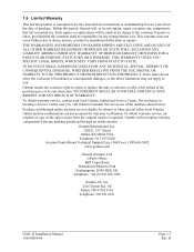
... Center. Liberty House Bull Copse Road Hounsdown Business Park Southampton, SO40 9RB, UK Telephone: +44 (0) 870 850 1243 Garmin AT, Inc. 2345 Turner Rd., SE Salem, OR 97302 USA Telephone: 503.581.8101 GAD 43 Installation Manual 190-00899-00 Page 1-7 Rev. For assistance in locating a Service Center near you . Products sold through...
... Center. Liberty House Bull Copse Road Hounsdown Business Park Southampton, SO40 9RB, UK Telephone: +44 (0) 870 850 1243 Garmin AT, Inc. 2345 Turner Rd., SE Salem, OR 97302 USA Telephone: 503.581.8101 GAD 43 Installation Manual 190-00899-00 Page 1-7 Rev. For assistance in locating a Service Center near you . Products sold through...

Installation Manual
Page 18
B GAD 43 Installation Manual 190-00899-00 This page intentionally left blank Page 1-8 Rev.
B GAD 43 Installation Manual 190-00899-00 This page intentionally left blank Page 1-8 Rev.
Installation Manual
Page 19
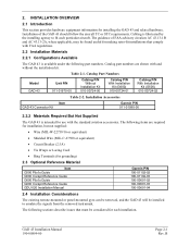
... the signals from the removed instrument. Installation Accessories Item GAD 43 Connector Kit Garmin P/N 011-01990-00 2.2.2 Materials Required But Not Supplied The GAD 43 is available under the following items are shown with the standard aviation accessories. GAD 43 Installation Manual 190-00899-00 Page 2-1 Rev. Catalog... Guide GDU 620 Installation Manual Garmin P/N 190-01102-02 190-01102-03 190-00601-02 190-00601-03 190-00601-04 2.4 Installation Considerations The existing remote-mounted or panel-mounted gyro can be removed, and the GAD 43 will be considered for use with...
... the signals from the removed instrument. Installation Accessories Item GAD 43 Connector Kit Garmin P/N 011-01990-00 2.2.2 Materials Required But Not Supplied The GAD 43 is available under the following items are shown with the standard aviation accessories. GAD 43 Installation Manual 190-00899-00 Page 2-1 Rev. Catalog... Guide GDU 620 Installation Manual Garmin P/N 190-01102-02 190-01102-03 190-00601-02 190-00601-03 190-00601-04 2.4 Installation Considerations The existing remote-mounted or panel-mounted gyro can be removed, and the GAD 43 will be considered for use with...

Installation Manual
Page 20
...00 Do not attempt to AWG #20 wire (P431). If mounting the GAD 43 on aircraft circuit breaker layout, length of wiring, current draw of GAD 43 Page 2-2 Rev. If mounting the GAD 43 flat, a minimum of the GAD 43 is specified on its side, a minimum of heat, RF or EMI ... common circuit breaker, sizing and wire gauge is ample space for all connections unless otherwise specified by the aircraft manufacturer or Garmin. Avoid sharp bends in the GAD 43 Environmental Qualification Form (EQF), P/N 005-00496-07. Side and Flat Mounting of units, and internal unit protection characteristics....
...00 Do not attempt to AWG #20 wire (P431). If mounting the GAD 43 on aircraft circuit breaker layout, length of wiring, current draw of GAD 43 Page 2-2 Rev. If mounting the GAD 43 flat, a minimum of the GAD 43 is specified on its side, a minimum of heat, RF or EMI ... common circuit breaker, sizing and wire gauge is ample space for all connections unless otherwise specified by the aircraft manufacturer or Garmin. Avoid sharp bends in the GAD 43 Environmental Qualification Form (EQF), P/N 005-00496-07. Side and Flat Mounting of units, and internal unit protection characteristics....

Installation Manual
Page 21
...mounted in the GDU 620 configuration module and will be found in the GAD 43 Environmental Qualification Form (EQF), P/N 005-00496-07. The mounting surface should be retained when the GAD 43 is sufficient length to Garmin until the carrier has authorized the claim. After configuration, power up ...the system including GDU 620 and GAD 43 and verify that there is replaced with a new unit. NOTE The ...
...mounted in the GDU 620 configuration module and will be found in the GAD 43 Environmental Qualification Form (EQF), P/N 005-00496-07. The mounting surface should be retained when the GAD 43 is sufficient length to Garmin until the carrier has authorized the claim. After configuration, power up ...the system including GDU 620 and GAD 43 and verify that there is replaced with a new unit. NOTE The ...
