Installation Manual
Page 3
... USA Telephone: 913-397-8200 Aviation Dealer Technical Support Line (Toll Free): (888) 606 5482 http://www.garmin.com Garmin (Europe) Ltd. Garmin hereby grants permission to download a single copy of this manual and of any revision to this...Garmin. GAD 43 Installation Manual 190-00899-00 Page A Rev. Liberty House Bull Copse Road Hounsdown Business Park Southampton, SO40 9RB, UK Telephone: +44 (0) 870 850 1243 Garmin AT, Inc. 2345 Turner Rd., SE Salem, OR 97302 USA Telephone: 503.581.8101 RECORD OF REVISIONS Revision A B Revision Date 4/30/09 5/7/09 Description Initial Release Changed...
... USA Telephone: 913-397-8200 Aviation Dealer Technical Support Line (Toll Free): (888) 606 5482 http://www.garmin.com Garmin (Europe) Ltd. Garmin hereby grants permission to download a single copy of this manual and of any revision to this...Garmin. GAD 43 Installation Manual 190-00899-00 Page A Rev. Liberty House Bull Copse Road Hounsdown Business Park Southampton, SO40 9RB, UK Telephone: +44 (0) 870 850 1243 Garmin AT, Inc. 2345 Turner Rd., SE Salem, OR 97302 USA Telephone: 503.581.8101 RECORD OF REVISIONS Revision A B Revision Date 4/30/09 5/7/09 Description Initial Release Changed...
Installation Manual
Page 5
... nationals inside or outside the United States without first obtaining an export license. B INFORMATION SUBJECT TO EXPORT CONTROL LAWS This document may contain information which is being provided in accordance with California's Proposition 65. GAD 43 Installation Manual 190-00899-00 Page i ... information, please refer to cause cancer, birth defects, or reproductive harm. Some differences in operation may not be exported, released or disclosed to be observed when comparing the information in part of software version 2.00. This manual reflects the operation of this manual ...
... nationals inside or outside the United States without first obtaining an export license. B INFORMATION SUBJECT TO EXPORT CONTROL LAWS This document may contain information which is being provided in accordance with California's Proposition 65. GAD 43 Installation Manual 190-00899-00 Page i ... information, please refer to cause cancer, birth defects, or reproductive harm. Some differences in operation may not be exported, released or disclosed to be observed when comparing the information in part of software version 2.00. This manual reflects the operation of this manual ...
Installation Manual
Page 7
... ...2-1 2.2.1 Configurations Available ...2-1 2.2.2 Materials Required But Not Supplied 2-1 2.3 Optional Reference Material...2-1 2.4 Installation Considerations...2-1 2.4.1 Cabling and Wiring ...2-2 2.4.2 Cooling Requirements...2-2 2.4.3 Mounting Requirements...2-2 3. B SYSTEM INTERCONNECTS...4-1 4.1 Pin Function List...4-1 4.1.1 P431 Connector...4-1 4.2 Functional Descriptions ...4-3 4.2.1 Power...4-3 4.2.2 Power Supply Outputs...4-3 4.2.3 Serial Data...4-3 4.2.4 Gyro Emulation Interfaces 4-4 4.2.5 Baro Correction Outputs ...4-6 4.2.6 Discretes...4-6 GAD 43 Installation Manual 190-00899...
... ...2-1 2.2.1 Configurations Available ...2-1 2.2.2 Materials Required But Not Supplied 2-1 2.3 Optional Reference Material...2-1 2.4 Installation Considerations...2-1 2.4.1 Cabling and Wiring ...2-2 2.4.2 Cooling Requirements...2-2 2.4.3 Mounting Requirements...2-2 3. B SYSTEM INTERCONNECTS...4-1 4.1 Pin Function List...4-1 4.1.1 P431 Connector...4-1 4.2 Functional Descriptions ...4-3 4.2.1 Power...4-3 4.2.2 Power Supply Outputs...4-3 4.2.3 Serial Data...4-3 4.2.4 Gyro Emulation Interfaces 4-4 4.2.5 Baro Correction Outputs ...4-6 4.2.6 Discretes...4-6 GAD 43 Installation Manual 190-00899...
Installation Manual
Page 8
... Relays...4-7 5. GAD 43 CG and Dimensions B-4 Figure C-1. GAD 43 Power Interconnect C-3 Figure C-2. GAD 43 Heading Interconnect C-6 Figure C-5. Catalog Part Numbers...2-1 Table 2-2. B GAD 43 Installation Manual 190-00899-00 GAD 43 Unit and Connector B-3 Figure B-2. Socket Contact Part Numbers 3-2 Table 3-2. Gyro Emulation Types...5-3 Page iv Rev. SYSTEM CONFIGURATION AND CHECKOUT 5-1 5.1 Post Installation Power Check ...5-1 5.2 GAD 43 Software Loading ...5-1 5.3 Initial Configuration of GAD 43 2-2 Figure 3-1. GAD 43 Panel Mount Gyro Replacement Interconnect C-4 Figure...
... Relays...4-7 5. GAD 43 CG and Dimensions B-4 Figure C-1. GAD 43 Power Interconnect C-3 Figure C-2. GAD 43 Heading Interconnect C-6 Figure C-5. Catalog Part Numbers...2-1 Table 2-2. B GAD 43 Installation Manual 190-00899-00 GAD 43 Unit and Connector B-3 Figure B-2. Socket Contact Part Numbers 3-2 Table 3-2. Gyro Emulation Types...5-3 Page iv Rev. SYSTEM CONFIGURATION AND CHECKOUT 5-1 5.1 Post Installation Power Check ...5-1 5.2 GAD 43 Software Loading ...5-1 5.3 Initial Configuration of GAD 43 2-2 Figure 3-1. GAD 43 Panel Mount Gyro Replacement Interconnect C-4 Figure...
Installation Manual
Page 9
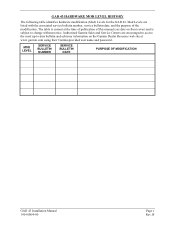
... of this manual (see date on the Garmin Dealer Resource web site at the time of publication of the modification. B The table is subject to -date bulletin and advisory information on front cover) and is current at www.garmin.com using their Garmin-provided user name and password. MOD LEVEL SERVICE BULLETIN NUMBER SERVICE BULLETIN DATE PURPOSE OF MODIFICATION GAD 43 Installation Manual 190-00899...
... of this manual (see date on the Garmin Dealer Resource web site at the time of publication of the modification. B The table is subject to -date bulletin and advisory information on front cover) and is current at www.garmin.com using their Garmin-provided user name and password. MOD LEVEL SERVICE BULLETIN NUMBER SERVICE BULLETIN DATE PURPOSE OF MODIFICATION GAD 43 Installation Manual 190-00899...
Installation Manual
Page 11
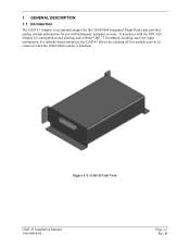
1. B For attitude-based autopilots, the GAD 43 allows the existing ADI or attitude gyro to be removed when the G500/G600 system is an optional adapter for the G500/G600 Integrated Flight Decks that provides analog attitude information for use with third-party autopilot systems. It interfaces with the GDU 620 Display for configuration and alerting, and with the GRS 77 for attitude, heading, and yaw input information. GENERAL DESCRIPTION 1.1 Introduction The GAD 43 Adapter is installed. GAD 43 Unit View GAD 43 Installation Manual 190-00899-00 Page 1-1 Rev. Figure 1-1.
1. B For attitude-based autopilots, the GAD 43 allows the existing ADI or attitude gyro to be removed when the G500/G600 system is an optional adapter for the G500/G600 Integrated Flight Decks that provides analog attitude information for use with third-party autopilot systems. It interfaces with the GDU 620 Display for configuration and alerting, and with the GRS 77 for attitude, heading, and yaw input information. GENERAL DESCRIPTION 1.1 Introduction The GAD 43 Adapter is installed. GAD 43 Unit View GAD 43 Installation Manual 190-00899-00 Page 1-1 Rev. Figure 1-1.
Installation Manual
Page 12
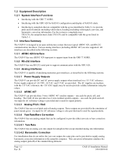
... 77 AHRS. • Interfacing with the GDU 620 for GAD 43 configuration and display of GAD 43 alerts. • Interfacing to autopilots that are described in the following sections. 1.3.3.1 Power Supply Outputs The GAD 43 can provide DC and AC power supply outputs when interfaced to provide validity information using the relays. 1.3.3.2 ARINC 407 The GAD 43 can provide three 3-wire ARINC 407 synchro outputs - For the system...
... 77 AHRS. • Interfacing with the GDU 620 for GAD 43 configuration and display of GAD 43 alerts. • Interfacing to autopilots that are described in the following sections. 1.3.3.1 Power Supply Outputs The GAD 43 can provide DC and AC power supply outputs when interfaced to provide validity information using the relays. 1.3.3.2 ARINC 407 The GAD 43 can provide three 3-wire ARINC 407 synchro outputs - For the system...
Installation Manual
Page 13
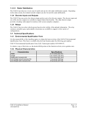
... the installing agency to obtain the latest revision of the GAD 43 Environmental Qualification Form. 1.3.3.5 Radar Stabilization The GAD 43 provides two 2-wire (one for pitch and one of the discrete outputs are available to support a wide-variety of configurations. 1.4 Technical Specifications 1.4.1 Environmental Qualification Form It is available directly from Garmin under the following part number: GAD 43 Environmental Qualification Form, EQF, Garmin part number 005...
... the installing agency to obtain the latest revision of the GAD 43 Environmental Qualification Form. 1.3.3.5 Radar Stabilization The GAD 43 provides two 2-wire (one for pitch and one of the discrete outputs are available to support a wide-variety of configurations. 1.4 Technical Specifications 1.4.1 Environmental Qualification Form It is available directly from Garmin under the following part number: GAD 43 Environmental Qualification Form, EQF, Garmin part number 005...
Installation Manual
Page 15
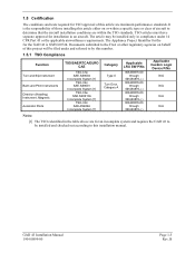
... out according to this installation manual. B Documents submitted to the FAA or other regulatory agencies on or within a specific type or class of aircraft to by this number. 1.5.1 TSO Compliance Function Turn and Slip Instrument Bank and Pitch Instruments Direction (Heading) Instrument, Magnetic Automatic Pilots TSO/SAE/RTCA/EURO CAE TSO-C3e SAE AS8004 Incomplete System [1] TSO-C4c SAE AS8001 Incomplete...
... out according to this installation manual. B Documents submitted to the FAA or other regulatory agencies on or within a specific type or class of aircraft to by this number. 1.5.1 TSO Compliance Function Turn and Slip Instrument Bank and Pitch Instruments Direction (Heading) Instrument, Magnetic Automatic Pilots TSO/SAE/RTCA/EURO CAE TSO-C3e SAE AS8004 Incomplete System [1] TSO-C4c SAE AS8001 Incomplete...
Installation Manual
Page 17
... numbers shown below. To obtain warranty service, contact your local Garmin Authorized Service Center. 1.6 Limited Warranty This Garmin product is required. Garmin will , at its sole option, repair or replace any package purchased through online auctions are not accepted for any transportation cost. Garmin International, Inc. 1200 E. 151st Street Olathe, KS 66062 USA Telephone: 913.397.8200 Aviation Panel-Mount Technical Support Line (Toll Free...
... numbers shown below. To obtain warranty service, contact your local Garmin Authorized Service Center. 1.6 Limited Warranty This Garmin product is required. Garmin will , at its sole option, repair or replace any package purchased through online auctions are not accepted for any transportation cost. Garmin International, Inc. 1200 E. 151st Street Olathe, KS 66062 USA Telephone: 913.397.8200 Aviation Panel-Mount Technical Support Line (Toll Free...
Installation Manual
Page 19
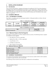
... related hardware. Cabling is available under the following part numbers. The following items are shown with FAA regulations. 2.2 Installation Materials 2.2.1 Configurations Available The GAD 43 is fabricated by the installing agency to emulate the signals from the removed instrument. The following sections describe issues that must be considered for grounding) 2.3 Optional Reference Material Item G500 Pilot's Guide G500 Cockpit Reference Guide G600 Pilot's Guide G600 Cockpit Reference Guide GDU 620 Installation Manual Garmin P/N 190...
... related hardware. Cabling is available under the following part numbers. The following items are shown with FAA regulations. 2.2 Installation Materials 2.2.1 Configurations Available The GAD 43 is fabricated by the installing agency to emulate the signals from the removed instrument. The following sections describe issues that must be considered for grounding) 2.3 Optional Reference Material Item G500 Pilot's Guide G500 Cockpit Reference Guide G600 Pilot's Guide G600 Cockpit Reference Guide GDU 620 Installation Manual Garmin P/N 190...

Installation Manual
Page 20
... on its side. Side and Flat Mounting of units, and internal unit protection characteristics. B GAD 43 Installation Manual 190-00899-00 In cases where some installations have more than one unit on aircraft circuit breaker layout, length of wiring, current draw of GAD 43 Page 2-2 Rev. 2.4.1 Cabling and Wiring Use AWG #24 or larger wire for the cabling and mating connectors. Check that are compatible with the...
... on its side. Side and Flat Mounting of units, and internal unit protection characteristics. B GAD 43 Installation Manual 190-00899-00 In cases where some installations have more than one unit on aircraft circuit breaker layout, length of wiring, current draw of GAD 43 Page 2-2 Rev. 2.4.1 Cabling and Wiring Use AWG #24 or larger wire for the cabling and mating connectors. Check that are compatible with the...

Installation Manual
Page 21
... crimp connections with a new unit. 3. To justify a claim, save the original shipping container and all connections except for the rear D-sub connectors. The unit should be pressurized or unpressurized. If the unit was serviced or if a new unit is being installed, verify that no failure or error messages are required to allow for the installation of the connector. NOTE The installation configuration settings are stored in Section 1.4.3. Use...
... crimp connections with a new unit. 3. To justify a claim, save the original shipping container and all connections except for the rear D-sub connectors. The unit should be pressurized or unpressurized. If the unit was serviced or if a new unit is being installed, verify that no failure or error messages are required to allow for the installation of the connector. NOTE The installation configuration settings are stored in Section 1.4.3. Use...
Installation Manual
Page 22
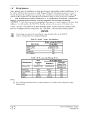
... installation. See APPENDIX C for interconnect wiring diagrams. CAUTION Check wiring connections for installation of electrical noise. The installer supplies and fabricates all input and output signals. Socket Contact Part Numbers Wire Gauge Garmin P/N Military P/N AMP Positronic ITT Cannon 50-pin connector (P431) 20-24 AWG 336-00022-00 M39029/63-368 N/A N/A N/A Table 3-2. Page 3-2 Rev. 3.5.1 Wiring Harness Allow adequate space for errors before connecting the cables to the GAD 43. Construct the wiring...
... installation. See APPENDIX C for interconnect wiring diagrams. CAUTION Check wiring connections for installation of electrical noise. The installer supplies and fabricates all input and output signals. Socket Contact Part Numbers Wire Gauge Garmin P/N Military P/N AMP Positronic ITT Cannon 50-pin connector (P431) 20-24 AWG 336-00022-00 M39029/63-368 N/A N/A N/A Table 3-2. Page 3-2 Rev. 3.5.1 Wiring Harness Allow adequate space for errors before connecting the cables to the GAD 43. Construct the wiring...
Installation Manual
Page 26
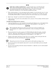
... the prepared cable assembly (11) and connect the wire (13) to be attached. 4. These solder sleeves come with solder sleeves. Repeat steps 1 through the holes on the Shield Block and threading into the connector backshell (1). B GAD 43 Installation Manual 190-00899-00 For detailed instructions on the backshell (1). (See Figure 3-1). CAUTION When mounting the slide lock, use , refer to the backshell...
... the prepared cable assembly (11) and connect the wire (13) to be attached. 4. These solder sleeves come with solder sleeves. Repeat steps 1 through the holes on the Shield Block and threading into the connector backshell (1). B GAD 43 Installation Manual 190-00899-00 For detailed instructions on the backshell (1). (See Figure 3-1). CAUTION When mounting the slide lock, use , refer to the backshell...

Installation Manual
Page 27
... is need for actual aircraft maintenance requirements. For regulatory periodic functional checks, refer to ensure a good electrical connection. 6. If only a single wire is left or if only a single wire is recommended that a maximum of a ring terminal, #8, insulated, 14-16 AWG (MS25036-153). Install ring terminals (15) onto the wires (13), grouping wires as appropriate for the unit. APPENDIX B contains information on its...
... is need for actual aircraft maintenance requirements. For regulatory periodic functional checks, refer to ensure a good electrical connection. 6. If only a single wire is left or if only a single wire is recommended that a maximum of a ring terminal, #8, insulated, 14-16 AWG (MS25036-153). Install ring terminals (15) onto the wires (13), grouping wires as appropriate for the unit. APPENDIX B contains information on its...
Installation Manual
Page 32
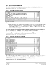
...outputs. DC pitch and roll outputs are capable of these pins. The GAD 43 can convert an 115 VAC signal to support this conversion. See Section 4.2.4.3 for emulating gyros such as those used for configuration information. The GAD 43 provides synchro pitch, roll and heading outputs. An input for 10 VAC reference...B GAD 43 Installation Manual 190-00899-00 See APPENDIX C for wiring interconnect information to a 26 VAC reference if desired. Configuration determines the function of driving a 1 kΩ load. Page 4-4 Rev. 4.2.4 Gyro Emulation Interfaces The GAD 43...
...outputs. DC pitch and roll outputs are capable of these pins. The GAD 43 can convert an 115 VAC signal to support this conversion. See Section 4.2.4.3 for emulating gyros such as those used for configuration information. The GAD 43 provides synchro pitch, roll and heading outputs. An input for 10 VAC reference...B GAD 43 Installation Manual 190-00899-00 See APPENDIX C for wiring interconnect information to a 26 VAC reference if desired. Configuration determines the function of driving a 1 kΩ load. Page 4-4 Rev. 4.2.4 Gyro Emulation Interfaces The GAD 43...

Installation Manual
Page 33
...; load. An input for wiring interconnect information to support this conversion. GAD 43 Installation Manual 190-00899-00 Page 4-5 Rev. The GAD 43 provides weather radar pitch and roll stabilization outputs. When the GAD 43 is also provided. See APPENDIX C for 26 VAC reference voltage is configured to a 26 VAC reference if desired. Refer to Section 5.3.1.1 for wiring interconnect information to support this conversion. The weather radar (stabilization) outputs are active. B The GAD...
...; load. An input for wiring interconnect information to support this conversion. GAD 43 Installation Manual 190-00899-00 Page 4-5 Rev. The GAD 43 provides weather radar pitch and roll stabilization outputs. When the GAD 43 is also provided. See APPENDIX C for 26 VAC reference voltage is configured to a 26 VAC reference if desired. Refer to Section 5.3.1.1 for wiring interconnect information to support this conversion. The weather radar (stabilization) outputs are active. B The GAD...
Installation Manual
Page 34
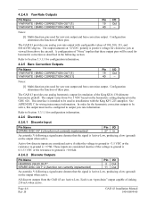
... the aircraft. Refer to 5 VDC based on the barometric setting displayed on the output when active. Refer to output yaw rate information. Notes: [1] Multi-function pins used for the barometric correction outputs to be active, this output must not be used in the following section. In order for yaw rate output and baro correction output. Configuration determines the function of the King KEA-130 altimeter barometric pickoff. This interface...
... the aircraft. Refer to 5 VDC based on the barometric setting displayed on the output when active. Refer to output yaw rate information. Notes: [1] Multi-function pins used for the barometric correction outputs to be active, this output must not be used in the following section. In order for yaw rate output and baro correction output. Configuration determines the function of the King KEA-130 altimeter barometric pickoff. This interface...

Installation Manual
Page 37
... product information of the initial configuration, the GAD 43 functions must be enabled/disabled as specified in configuration mode by pressing and holding the ENT button while applying power. As part of the various LRUs. Ensure wiring is used to configure and checkout the installation of the connector. Check the movement of the GAD 43 NOTE To access and modify the GAD 43 configuration page, an Installer Unlock Card P/N 010...
... product information of the initial configuration, the GAD 43 functions must be enabled/disabled as specified in configuration mode by pressing and holding the ENT button while applying power. As part of the various LRUs. Ensure wiring is used to configure and checkout the installation of the connector. Check the movement of the GAD 43 NOTE To access and modify the GAD 43 configuration page, an Installer Unlock Card P/N 010...

