Manual/User Guide
Page 3
Use M3 screw for the mounting screw and the screw length should satisfy the specification in any direction. (2) Frame The MR head bias of the HDD disk enclosure (DE) is attached. When attaching the HDD to the system frame, do ... parts to Signal Ground (SG). The tightening torque must be mounted in Figure 3.2. 3.2 Mounting 3.2 Mounting For information on mounting, see the "FUJITSU 2.5-INCH HDD INTEGRATION GUIDANCE (C141-E144)." (1) Orientation The disk drives can be 0.49N•m (5kgf•cm). The mounting frame is connected to which the HDD is zero. C141-E262 3-3
Use M3 screw for the mounting screw and the screw length should satisfy the specification in any direction. (2) Frame The MR head bias of the HDD disk enclosure (DE) is attached. When attaching the HDD to the system frame, do ... parts to Signal Ground (SG). The tightening torque must be mounted in Figure 3.2. 3.2 Mounting 3.2 Mounting For information on mounting, see the "FUJITSU 2.5-INCH HDD INTEGRATION GUIDANCE (C141-E144)." (1) Orientation The disk drives can be 0.49N•m (5kgf•cm). The mounting frame is connected to which the HDD is zero. C141-E262 3-3
Manual/User Guide
Page 10
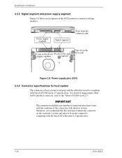
...P1 pins in the power S1 pins in the signal supply segment segment View from the connectors complying with the Serial ATA Revision 2.5 specification. 3-10 C141-E262 The connection reliability per number of insertion/extractions varies with the condition of host system for mating with the disk... drive must be compliant with the host system. For detail of the SATA interface connector and pin numbers. Therefore, we recommend that the customer...
...P1 pins in the power S1 pins in the signal supply segment segment View from the connectors complying with the Serial ATA Revision 2.5 specification. 3-10 C141-E262 The connection reliability per number of insertion/extractions varies with the condition of host system for mating with the disk... drive must be compliant with the host system. For detail of the SATA interface connector and pin numbers. Therefore, we recommend that the customer...
Manual/User Guide
Page 11
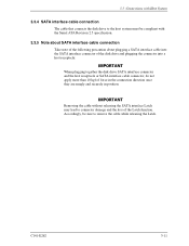
...Serial ATA Revision 2.5 specification. 3.3.5 Note about SATA interface cable connection Take note of the following precaution about plugging a SATA interface cable into the SATA interface connector of the disk drive and plugging the connector into a host receptacle: When plugging together the disk drive SATA interface connector and ...Latch. C141-E262 3-11 Accordingly, be compliant with Host System 3.3.4 SATA interface cable connection The cable that connects the disk drive to the host system must be sure to connector damage and the loss of force in the connection direction once they are ...
...Serial ATA Revision 2.5 specification. 3.3.5 Note about SATA interface cable connection Take note of the following precaution about plugging a SATA interface cable into the SATA interface connector of the disk drive and plugging the connector into a host receptacle: When plugging together the disk drive SATA interface connector and ...Latch. C141-E262 3-11 Accordingly, be compliant with Host System 3.3.4 SATA interface cable connection The cable that connects the disk drive to the host system must be sure to connector damage and the loss of force in the connection direction once they are ...
