Manual/User Guide
Page 3
The tightening torque must be mounted in Figure 3.2. IMPORTANT Use M3 screw for the mounting screw and the screw length should satisfy the specification in any direction. (2) Frame The MR head bias of the HDD disk enclosure (DE) is attached. C141-E254 3-3 The mounting frame is connected to ... the system frame to touch parts (cover and base) other than parts to Signal Ground (SG). 3.2 Mounting 3.2 Mounting For information on mounting, see the "FUJITSU 2.5-INCH HDD INTEGRATION GUIDANCE (C141-E144)." (1) Orientation The disk drives can be 0.49N•m (5kgf•cm).
The tightening torque must be mounted in Figure 3.2. IMPORTANT Use M3 screw for the mounting screw and the screw length should satisfy the specification in any direction. (2) Frame The MR head bias of the HDD disk enclosure (DE) is attached. C141-E254 3-3 The mounting frame is connected to ... the system frame to touch parts (cover and base) other than parts to Signal Ground (SG). 3.2 Mounting 3.2 Mounting For information on mounting, see the "FUJITSU 2.5-INCH HDD INTEGRATION GUIDANCE (C141-E144)." (1) Orientation The disk drives can be 0.49N•m (5kgf•cm).
Manual/User Guide
Page 10
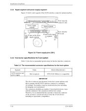
...the signal segment View from the several choices including its mating with the host system. Table 3.2 The recommended connector specifications for the host system Segment SATA interface and power supply Name Host receptacle Model (Manufacturer) 67492-0220 (Molex) or compatibles...the customer's system and select it from the PCA side Figure 3.8 Power supply pins (CN1) 3.3.3 Connector specifications for host system Table 3.2 lists the recommended specifications for the host interface connectors. Installation Conditions 3.3.2 Signal segment and power supply segment Figure 3.8 shows each ...
...the signal segment View from the several choices including its mating with the host system. Table 3.2 The recommended connector specifications for the host system Segment SATA interface and power supply Name Host receptacle Model (Manufacturer) 67492-0220 (Molex) or compatibles...the customer's system and select it from the PCA side Figure 3.8 Power supply pins (CN1) 3.3.3 Connector specifications for host system Table 3.2 lists the recommended specifications for the host interface connectors. Installation Conditions 3.3.2 Signal segment and power supply segment Figure 3.8 shows each ...
Manual/User Guide
Page 11
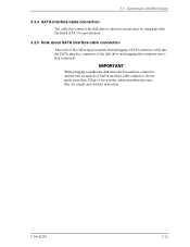
3.3 Connections with Host System 3.3.4 SATA interface cable connection The cable that connects the disk drive to the host system must be compliant with the Serial ATA 1.0a specification. 3.3.5 Note about SATA interface cable connection Take note of the following precaution about plugging a SATA interface cable into the SATA interface connector of the disk...
3.3 Connections with Host System 3.3.4 SATA interface cable connection The cable that connects the disk drive to the host system must be compliant with the Serial ATA 1.0a specification. 3.3.5 Note about SATA interface cable connection Take note of the following precaution about plugging a SATA interface cable into the SATA interface connector of the disk...
