Manual/User Guide
Page 1
C141-E144 C141-E250 3-1 CHAPTER 3 Installation Conditions 3.1 Dimensions 3.2 Mounting 3.3 Cable Connections 3.4 Jumper Settings This chapter gives the external dimensions, installation conditions, surface temperature conditions, cable connections, and switch settings of the hard disk drives. For information about handling this hard disk drive and the system installation procedure, refer to the following Integration Guide.
C141-E144 C141-E250 3-1 CHAPTER 3 Installation Conditions 3.1 Dimensions 3.2 Mounting 3.3 Cable Connections 3.4 Jumper Settings This chapter gives the external dimensions, installation conditions, surface temperature conditions, cable connections, and switch settings of the hard disk drives. For information about handling this hard disk drive and the system installation procedure, refer to the following Integration Guide.
Manual/User Guide
Page 10
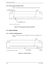
Figure 3.10 Jumper location 3-10 C141-E250 Installation Conditions 3.3.4 Power supply connector (CN1) Figure 3.9 shows the pin assignment of the jumpers to select drive configuration and functions. Figure 3.9 Power supply connector pins (CN1) 3.4 Jumper Settings 3.4.1 Location of setting jumpers Figure 3.10 shows the location of the power supply connector (CN1).
Figure 3.10 Jumper location 3-10 C141-E250 Installation Conditions 3.3.4 Power supply connector (CN1) Figure 3.9 shows the pin assignment of the jumpers to select drive configuration and functions. Figure 3.9 Power supply connector pins (CN1) 3.4 Jumper Settings 3.4.1 Location of setting jumpers Figure 3.10 shows the location of the power supply connector (CN1).
Manual/User Guide
Page 11
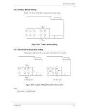
Open Figure 3.11 Factory default setting 3.4.3 Master drive-slave drive setting Master drive (disk drive #0) or slave drive (disk drive #1) is selected. Open 1 CA 2 DB Open (a) Master drive 1 CA Open Short 2 DB (b) Slave drive Figure 3.12 Jumper setting of master or slave drive Note: Pins A and C should be open. 3.4 Jumper Settings 3.4.2 Factory default setting Figure 3.11 shows the default setting position at the factory. C141-E250 3-11
Open Figure 3.11 Factory default setting 3.4.3 Master drive-slave drive setting Master drive (disk drive #0) or slave drive (disk drive #1) is selected. Open 1 CA 2 DB Open (a) Master drive 1 CA Open Short 2 DB (b) Slave drive Figure 3.12 Jumper setting of master or slave drive Note: Pins A and C should be open. 3.4 Jumper Settings 3.4.2 Factory default setting Figure 3.11 shows the default setting position at the factory. C141-E250 3-11
Manual/User Guide
Page 13
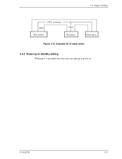
C141-E250 3-13 3.4 Jumper Settings drive Figure 3.15 Example (2) of cable select drive 3.4.5 Power up in standby setting When pin C is grounded, the drive does not spin up at power on.
C141-E250 3-13 3.4 Jumper Settings drive Figure 3.15 Example (2) of cable select drive 3.4.5 Power up in standby setting When pin C is grounded, the drive does not spin up at power on.

