Fujitsu MHK2120AT - Mobile 12 GB Hard Drive Support and Manuals
Get Help and Manuals for this Fujitsu item
View All Support Options Below
Free Fujitsu MHK2120AT manuals!
Problems with Fujitsu MHK2120AT?
Ask a Question
Free Fujitsu MHK2120AT manuals!
Problems with Fujitsu MHK2120AT?
Ask a Question
Popular Fujitsu MHK2120AT Manual Pages
Manual/User Guide - Page 6

... of the definitions used in which they operate. CHAPTER 3 Installation Conditions This chapter describes the external dimensions, installation conditions, and switch settings of the MHJ Series and MHK Series. This manual describes the specifications and functions of the drives and explains in this manual. CHAPTER 2 Device Configuration This chapter describes the internal configurations...
Manual/User Guide - Page 15
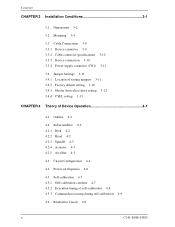
... 3 Installation Conditions 3-1
3.1 Dimensions 3-2
3.2 Mounting 3-4
3.3 Cable Connections 3-9 3.3.1 Device connector 3-9 3.3.2 Cable connector specifications 3-10 3.3.3 Device connection 3-10 3.3.4 Power supply connector (CN1) 3-11
3.4 Jumper Settings 3-11 3.4.1 Location of setting jumpers 3-11 3.4.2 Factory default setting 3-12 3.4.3 Master drive-slave drive setting 3-12 3.4.4 CSEL setting 3-13...
Manual/User Guide - Page 19
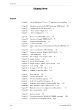
... Surface temperature measurement points (Sample: MHJ2181AT)
3-7 Figure 3.6 Service area (Sample: MHJ2181AT) 3-8 Figure 3.7 Connector locations (Sample: MHJ2181AT) 3-9 Figure 3.8 Cable connections 3-10 Figure 3.9 Power supply connector pins (CN1) 3-11 Figure 3.10 Jumper location 3-11 Figure 3.11 Factory default setting 3-12 Figure 3.12 Jumper setting of master or slave device 3-12 Figure 3.13 CSEL...
Manual/User Guide - Page 30
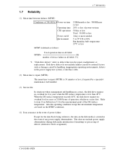
.../month or less 3000H/years or less 20% or less of power-on the disk media is less than 48°C. Refer to defects that involve repair, readjustment, or replacement.
When the DE surface temperature exceeds 48°C, the disk drives requires no overhaul for the measurement point of device failure in the event of...
Manual/User Guide - Page 38
C141-E088-03EN
3-1
CHAPTER 3 Installation Conditions
3.1
Dimensions
3.2
Mounting
3.3
Cable Connections
3.4
Jumper Settings
This chapter gives the external dimensions, installation conditions, surface temperature conditions, cable connections, and switch settings of the hard disk drives.
Manual/User Guide - Page 48
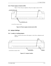
Figure 3.10 Jumper location
C141-E088-03EN
3-11 Figure 3.9 Power supply connector pins (CN1)
3.4 Jumper Settings
3.4.1 Location of setting jumpers Figure 3.10 shows the location of the power supply connector (CN1).
3.4 Jumper Settings
3.3.4 Power supply connector (CN1) Figure 3.9 shows the pin assignment of the jumpers to select drive configuration and functions.
Manual/User Guide - Page 49
... Factory default setting
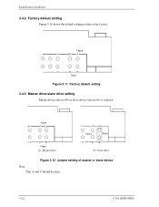
3.4.3 Master drive-slave drive setting Master device (device #0) or slave device (device #1) is selected.
Open
1
CA
2
DB
Open
(a) Master drive
1
CA
Open
Short
2
DB
(b) Slave drive
Figure 3.12 Jumper setting of master or slave device
Note: Pins A and C should be open.
3-12
C141-E088-03EN Installation Conditions 3.4.2 Factory default setting
Figure 3.11...
Manual/User Guide - Page 50
... a conductor.
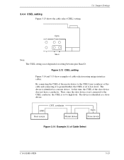
By connecting the CSEL of the master device to high level. The device is identified as a master device. 3.4.4 CSEL setting Figure 3.13 shows the cable select (CSEL) setting.
3.4 Jumper Settings
Open
1
CA
2
DB
Short
Note: The CSEL setting is set to the CSEL Line (conducer) of cable selection using unique interface cables. Figure 3.13 CSEL...
Manual/User Guide - Page 96
...sectors in maximum. The data stored in the buffer, and CRC code and ECC bytes are attempted irrespectively of the R bit setting. C141-E088-03EN
5-23
Number of the corresponding sector(s).
Data ...High, Cylinder Low, and Sector Number registers to an error, the remaining number of sectors of the last sector written.
If the head is set in this register.
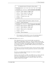
(5) WRITE SECTOR(S) (X'30' or ...
Manual/User Guide - Page 106
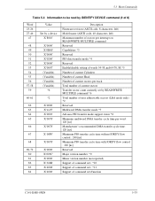
...Firmware revision (ASCII code, 8 characters, left) Model name (ASCII code, 40 characters, left) Maximum number of sectors per interrupt on READ/WRITE MULTIPLE command Reserved Capabilities *3 Reserved PIO data transfer mode *4 Reserved Enable/disable setting... number *9 Minor version number (not reported) Support of command sets *10 Support of command sets *11 Support of 8)
Word 23-26 27-46
47
...
Manual/User Guide - Page 109
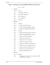
... the Host Protected Area feature set .
Bit 5: '1' = Supports the write cache function.
Bit 0: '1' = Supports the SMART feature set . Bit 8: '1' = Supports the SERVICE interrupt. Bit 7: '1' = Supports the release interrupt.
Bit 3: '1' = Supports the power management feature set .
Bit 1: '1' = Supports the Security Mode feature set . Interface
Table 5.4 Information to be...
Manual/User Guide - Page 110

...*12 WORD 85
Bits 15-9 : Same definition as WORD 82. Bit 8 : '1' = Enables the SERVICE interrupt.
Bit 3: '1' = Enables the Advanced Power Management function. Bit 6: '1' = Enables the read by IDENTIFY DEVICE command (6 of 8)
Bit 5: '1' = Supports the Power-Up In Standby set .
Bits 4-2: '1' = Same definition as WORD 82. Bit 4: '1' = Enables the Removable Media Status...
Manual/User Guide - Page 159

... DMA Mode 2 shall also support Ultra DMA Modes 0 and 1. When this data strobe signal are used by the same agent (either to provide new functions during an Ultra DMA data in the SET FEATURES command shall be satisfied.
During an Ultra DMA burst a sender shall always drive data onto the bus, and after...
Manual/User Guide - Page 221
... guard band 4-18 Input voltage 1-5 Installation condition 3-1 Insurance failure threshold 5-66 Interface 1-3, 5-1 Interface signal 5-2 Invalidating caching data 6-15
J
Jumper location 3-11 Jumper setting 3-11
L
Large capacity 1-2 LBA mode 6-9 Limitation of mounting 3-5 Logical address 6-8 Logical interface 5-6
M
Master 1-3 Master drive setting 3-12 Master password 5-74 Mean time between failures...
Manual/User Guide - Page 222

... 5-70 SECURITY ERASE UNIT 5-71 SECURITY FREEZE LOCK 5-72 SECURITY SET PASSWORD 5-74 SECURITY UNLOCK 5-75 SEEK 5-29 Seek operation 4-20 Seek to specified cylinder 4-15 Self-calibration 4-7 Self-calibration content 4-7 Self-diagnosis 1-3 Sensing and compensating for external force
4-7 Sequential command 6-17 Sequential hit 6-19 Sequential read 6-17 Service area 3-8 Service life 1-9 Servo A 4-19
IN-3
Fujitsu MHK2120AT Reviews
We have not received any reviews for Fujitsu yet.