
Manual/User Guide
Page 6
...describes the MHG Series and MHH Series, 2.5-inch hard disk drives. These drives have a built-in controller that the reader has a basic knowledge of hard disk drives and their implementations in computer systems. This manual consists... of seven chapters and sections explaining the special terminology and abbreviations used in this manual: Overview of Manual CHAPTER 1 Device Overview This chapter gives an overview of the drives and explains in which they operate. This manual describes the specifications...
...describes the MHG Series and MHH Series, 2.5-inch hard disk drives. These drives have a built-in controller that the reader has a basic knowledge of hard disk drives and their implementations in computer systems. This manual consists... of seven chapters and sections explaining the special terminology and abbreviations used in this manual: Overview of Manual CHAPTER 1 Device Overview This chapter gives an overview of the drives and explains in which they operate. This manual describes the specifications...

Manual/User Guide
Page 15
Contents CHAPTER 3 Installation Conditions 3-1 3.1 Dimensions 3-2 3.2 Mounting 3-4 3.3 Cable Connections 3-9 3.3.1 Device connector 3-9 3.3.2 Cable connector specifications 3-10 3.3.3 Device connection 3-10 3.3.4 Power supply connector (CN1) 3-11 3.4 Jumper Settings 3-11 3.4.1 Location of setting jumpers 3-11 3.4.2 Factory default setting 3-12 3.4.3 Master drive-slave drive setting 3-12 3.4.4 CSEL setting 3-13 CHAPTER 4 Theory of Device Operation 4-1 4.1 Outline 4-2 4.2 Subassemblies 4-2 4.2.1 Disk 4-2 4.2.2 Head 4-2 4.2.3 Spindle 4-3 4.2.4 Actuator 4-3 4.2.5 Air filter...
Contents CHAPTER 3 Installation Conditions 3-1 3.1 Dimensions 3-2 3.2 Mounting 3-4 3.3 Cable Connections 3-9 3.3.1 Device connector 3-9 3.3.2 Cable connector specifications 3-10 3.3.3 Device connection 3-10 3.3.4 Power supply connector (CN1) 3-11 3.4 Jumper Settings 3-11 3.4.1 Location of setting jumpers 3-11 3.4.2 Factory default setting 3-12 3.4.3 Master drive-slave drive setting 3-12 3.4.4 CSEL setting 3-13 CHAPTER 4 Theory of Device Operation 4-1 4.1 Outline 4-2 4.2 Subassemblies 4-2 4.2.1 Disk 4-2 4.2.2 Head 4-2 4.2.3 Spindle 4-3 4.2.4 Actuator 4-3 4.2.5 Air filter...

Manual/User Guide
Page 20
...data transfer 5-79 Figure 5.8 An example of generation of parallel CRC 5-93 Figure 5.9 Ultra DMA termination with pull-up or pull-down 5-94 Figure 5.10 Data transfer timing 5-96 Figure 5.11 Single word DMA data transfer timing (mode 2) 5-97 Figure 5.12 Multiword DMA data transfer timing (mode 2) 5-98...) 6-9 Figure 6.7 Sector slip processing 6-12 Figure 6.8 Alternate cylinder assignment 6-13 Figure 6.9 Data buffer configuration 6-14 Table 1.1 Table 1.2 Table 1.3 Table 1.4 Table 1.5 Table 1.6 Specifications 1-4 Model names and product numbers 1-5 Current and power dissipation 1-6 Environmental...
...data transfer 5-79 Figure 5.8 An example of generation of parallel CRC 5-93 Figure 5.9 Ultra DMA termination with pull-up or pull-down 5-94 Figure 5.10 Data transfer timing 5-96 Figure 5.11 Single word DMA data transfer timing (mode 2) 5-97 Figure 5.12 Multiword DMA data transfer timing (mode 2) 5-98...) 6-9 Figure 6.7 Sector slip processing 6-12 Figure 6.8 Alternate cylinder assignment 6-13 Figure 6.9 Data buffer configuration 6-14 Table 1.1 Table 1.2 Table 1.3 Table 1.4 Table 1.5 Table 1.6 Specifications 1-4 Model names and product numbers 1-5 Current and power dissipation 1-6 Environmental...

Manual/User Guide
Page 21
Contents Table 3.1 Surface temperature measurement points and standard values 3-7 Table 3.2 Cable connector specifications 3-10 Table 4.1 Self-calibration execution timechart 4-9 Table 4.2 Write precompensation algorithm 4-10 Table 5.1 Signal assignment on the interface connector 5-3 Table 5.2 I/O registers 5-7 Table 5.3 Command code ...Table 5.8 Format of device attribute value data 5-59 Table 5.9 Format of insurance failure threshold value data 5-60 Table 5.10 Contents of security password 5-64 Table 5.11 Contents of SECURITY SET PASSWORD data 5-68 Table 5.12 Relationship between combination ...
Contents Table 3.1 Surface temperature measurement points and standard values 3-7 Table 3.2 Cable connector specifications 3-10 Table 4.1 Self-calibration execution timechart 4-9 Table 4.2 Write precompensation algorithm 4-10 Table 5.1 Signal assignment on the interface connector 5-3 Table 5.2 I/O registers 5-7 Table 5.3 Command code ...Table 5.8 Format of device attribute value data 5-59 Table 5.9 Format of insurance failure threshold value data 5-60 Table 5.10 Contents of security password 5-64 Table 5.11 Contents of SECURITY SET PASSWORD data 5-68 Table 5.12 Relationship between combination ...

Manual/User Guide
Page 22
The MHG Series and MHH Series are 2.5-inch hard disk drives with built-in this chapter, and specifications and power requirement are described. C141-E070-01EN 1-1 These disk drives use the AT-bus hard disk interface protocol and are compact and reliable. CHAPTER 1 Device Overview 1.1 Features 1.2 Device Specifications 1.3 Power Requirements 1.4 Environmental Specifications 1.5 Acoustic Noise 1.6 Shock and Vibration 1.7 Reliability 1.8 Error Rate 1.9 Media Defects Overview and features are described in disk controllers.
The MHG Series and MHH Series are 2.5-inch hard disk drives with built-in this chapter, and specifications and power requirement are described. C141-E070-01EN 1-1 These disk drives use the AT-bus hard disk interface protocol and are compact and reliable. CHAPTER 1 Device Overview 1.1 Features 1.2 Device Specifications 1.3 Power Requirements 1.4 Environmental Specifications 1.5 Acoustic Noise 1.6 Shock and Vibration 1.7 Reliability 1.8 Error Rate 1.9 Media Defects Overview and features are described in disk controllers.
Manual/User Guide
Page 25
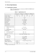
...) Typ.: 5 sec • Stop (at Power Down) Typ.: 5 sec Interface ATA-4 (Max. Table 1.1 Specifications (1/2) MHG2102AT MHH2064AT MHH2048AT MHH2032AT Format Capacity (*1) 10.0 GB 6.4 GB 4.3 GB 3.2 GB Number of Heads 6 4 3 2 Number of the disk drives (MHG2102AT/MHH2064AT/ MHH2048AT/MHH2032AT). Device Overview 1.2 Device Specifications 1.2.1 Specifications summary Table 1.1 shows the specfications of Cylinders (User) 11,173 Bytes per Sector 512 Recording Method (16/17) EPR4ML...
...) Typ.: 5 sec • Stop (at Power Down) Typ.: 5 sec Interface ATA-4 (Max. Table 1.1 Specifications (1/2) MHG2102AT MHH2064AT MHH2048AT MHH2032AT Format Capacity (*1) 10.0 GB 6.4 GB 4.3 GB 3.2 GB Number of Heads 6 4 3 2 Number of the disk drives (MHG2102AT/MHH2064AT/ MHH2048AT/MHH2032AT). Device Overview 1.2 Device Specifications 1.2.1 Specifications summary Table 1.1 shows the specfications of Cylinders (User) 11,173 Bytes per Sector 512 Recording Method (16/17) EPR4ML...
Manual/User Guide
Page 26
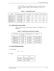
...product numbers Model Name MHG2102AT MHH2064AT MHH2048AT MHH2032AT Capacity (user area) 10.0 GB 6.4 GB 4.8 GB 3.2 GB Mounting screw Order No. of Sectors 63 63 63 63 1.2.2 Model and product number Table 1.2 lists the model names and product numbers of Cylinder 16,383 13,424 10,068 6,307 No.... as follows. 1.3 Power Requirements Under the CHS mode (normal BIOS specification), formatted capacity, number of cylinders, number of heads, and number of Heads 16 15 15 16 No. Table 1.1 Specifications (2/2) Model MHG2102AT MHH2064AT MHH2048AT MHH2032AT Formatted Capacity 8,455.20 MB 6,495.06 MB ...
...product numbers Model Name MHG2102AT MHH2064AT MHH2048AT MHH2032AT Capacity (user area) 10.0 GB 6.4 GB 4.8 GB 3.2 GB Mounting screw Order No. of Sectors 63 63 63 63 1.2.2 Model and product number Table 1.2 lists the model names and product numbers of Cylinder 16,383 13,424 10,068 6,307 No.... as follows. 1.3 Power Requirements Under the CHS mode (normal BIOS specification), formatted capacity, number of cylinders, number of heads, and number of Heads 16 15 15 16 No. Table 1.1 Specifications (2/2) Model MHG2102AT MHH2064AT MHH2048AT MHH2032AT Formatted Capacity 8,455.20 MB 6,495.06 MB ...

Manual/User Guide
Page 28
... Thermal Gradient Humidity • Operating • Non-operating • Maximum Wet Bulb Altitude (relative to sea level) • Operating • Non-operating Specification 5°C to 55°C (ambient) 5°C to 60°C (disk enclosure surface) -40°C to 65°C 20°C/h or less ...40°C (Non-operating) -300 to 3,000 m -300 to be concerned with the power on /off sequence. 1.4 Environmental Specifications Table 1.4 lists the environmental specifications. These prevent data from being destroyed and eliminates the need to 12,000 m C141-E070-02EN 1-7 1.4 Environmental...
... Thermal Gradient Humidity • Operating • Non-operating • Maximum Wet Bulb Altitude (relative to sea level) • Operating • Non-operating Specification 5°C to 55°C (ambient) 5°C to 60°C (disk enclosure surface) -40°C to 65°C 20°C/h or less ...40°C (Non-operating) -300 to 3,000 m -300 to be concerned with the power on /off sequence. 1.4 Environmental Specifications Table 1.4 lists the environmental specifications. These prevent data from being destroyed and eliminates the need to 12,000 m C141-E070-02EN 1-7 1.4 Environmental...

Manual/User Guide
Page 29
... Sound Pressure • Idle mode (DRIVE READY) Specification 30 dBA typical at 1 m Note: Measure the noise from the cover top surface. 1.6 Shock and Vibration Table 1.6 lists the shock and vibration specification. Table 1.6 Shock and vibration specification Item Vibration (swept sine, one octave per minute) • Operating... • Non-operating Shock (half-sine pulse) • Operating • Non-operating Specification 5 to 500 Hz, 1.0G0-peak (MHG series) 5 to 400 Hz, 1.0G0-peak (MHH series) (without non-recovered errors) (9.8 m/...
... Sound Pressure • Idle mode (DRIVE READY) Specification 30 dBA typical at 1 m Note: Measure the noise from the cover top surface. 1.6 Shock and Vibration Table 1.6 lists the shock and vibration specification. Table 1.6 Shock and vibration specification Item Vibration (swept sine, one octave per minute) • Operating... • Non-operating Shock (half-sine pulse) • Operating • Non-operating Specification 5 to 500 Hz, 1.0G0-peak (MHG series) 5 to 400 Hz, 1.0G0-peak (MHH series) (without non-recovered errors) (9.8 m/...
Manual/User Guide
Page 34
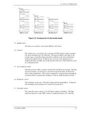
... dirt from entering. It improves data reliability by preventing errors caused by a direct drive Hall-less DC motor. (4) Actuator The actuator uses a revolving voice coil motor ...relies on the disk and is stopped, the head assembly stays in the specific CSS zone on the blower effect of the rotating disk. This system continuously...head. The highspeed microprocessor unit (MPU) achieves a high-performance AT controller. 2.1 Device Configuration Head 5 4 3 2 1 0 MHG2102AT Head 3 2 1 0 MHH2064AT 2 1 0 MHH2048AT Head 1 0 MHH2032AT Figure 2.2 Configuration of disk media heads (3) Spindle ...
... dirt from entering. It improves data reliability by preventing errors caused by a direct drive Hall-less DC motor. (4) Actuator The actuator uses a revolving voice coil motor ...relies on the disk and is stopped, the head assembly stays in the specific CSS zone on the blower effect of the rotating disk. This system continuously...head. The highspeed microprocessor unit (MPU) achieves a high-performance AT controller. 2.1 Device Configuration Head 5 4 3 2 1 0 MHG2102AT Head 3 2 1 0 MHH2064AT 2 1 0 MHH2048AT Head 1 0 MHH2032AT Figure 2.2 Configuration of disk media heads (3) Spindle ...

Manual/User Guide
Page 42
... MR head bias of B Figure 3.3 Mounting frame structure C141-E070-02EN 3-5 Use M3 screw for the mounting screw and the screw length should satisfy the specification in Figure 3.3. Note) These dimensions are recommended values; Bottom surface mounting DE 2 A Frame of system cabinet 2.5 2.5 2.5 Side surface 2.5 mounting PCA B Frame of system cabinet 3.0 or...
... MR head bias of B Figure 3.3 Mounting frame structure C141-E070-02EN 3-5 Use M3 screw for the mounting screw and the screw length should satisfy the specification in Figure 3.3. Note) These dimensions are recommended values; Bottom surface mounting DE 2 A Frame of system cabinet 2.5 2.5 2.5 Side surface 2.5 mounting PCA B Frame of system cabinet 3.0 or...

Manual/User Guide
Page 47
...because the interface is designed for ribbon cables and not for the cable connectors. Table 3.2 Cable connector specifications ATA interface and power supply cable (44-pin type) Name Cable socket (44-pin type) Model ... with wires that have become separated from the ribbon may cause crosstalk between signal lines. Figure 3.8 Cable connections 3-10 C141-E070-02EN Installation Conditions 3.3.2 Cable connector specifications Table 3.2 lists the recommended specifications for cables carrying differential signals. 3.3.3 Device connection Figure 3.8 shows how to connect the devices.
...because the interface is designed for ribbon cables and not for the cable connectors. Table 3.2 Cable connector specifications ATA interface and power supply cable (44-pin type) Name Cable socket (44-pin type) Model ... with wires that have become separated from the ribbon may cause crosstalk between signal lines. Figure 3.8 Cable connections 3-10 C141-E070-02EN Installation Conditions 3.3.2 Cable connector specifications Table 3.2 lists the recommended specifications for cables carrying differential signals. 3.3.3 Device connection Figure 3.8 shows how to connect the devices.

Manual/User Guide
Page 82
... 1 (slave device) Failed. If the command is , this register indicates the number of the master device is posted. (3) Features register (X'1F1') The Features register provides specific feature to complete the request from the host system. That is not completed scuccessfully, this register indicates the number of this register indicates the starting...
... 1 (slave device) Failed. If the command is , this register indicates the number of the master device is posted. (3) Features register (X'1F1') The Features register provides specific feature to complete the request from the host system. That is not completed scuccessfully, this register indicates the number of this register indicates the starting...

Manual/User Guide
Page 92
... requested sectors is not divided evenly (having the same number of sectors [block count]), as many full blocks as possible are transferred without interruption is specifed by SET MULTIPLE MODE command = 4 (number of the data block, and is not set at the sector where the error occurred. 5.3 Host Commands The implementation...
... requested sectors is not divided evenly (having the same number of sectors [block count]), as many full blocks as possible are transferred without interruption is specifed by SET MULTIPLE MODE command = 4 (number of the data block, and is not set at the sector where the error occurred. 5.3 Host Commands The implementation...

Manual/User Guide
Page 98
... register contains the number of sectors requested (not a number of the block count or a number of sectors in a block). The number of requested sectors is specifed by the SET MULTIPLE MODE command. If the number of sectors (block count) to the WRITE SECTOR(S) command.
... register contains the number of sectors requested (not a number of the block count or a number of sectors in a block). The number of requested sectors is specifed by the SET MULTIPLE MODE command. If the number of sectors (block count) to the WRITE SECTOR(S) command.

Manual/User Guide
Page 103
... are retained even after reset or power save operation regardless of the setting of heads minus 1") per cylinder with the CHS mode specification. The parameters set the number of sectors per track and the maximum head number (maximum head number is "number of disabling the... reverting to default setting. In LBA mode The device ignores the L bit specification and operates with this command, the device sets the BSY bit of this command. Interface At command issuance (I/O registers setting contents) 1F7 (CM...
... are retained even after reset or power save operation regardless of the setting of heads minus 1") per cylinder with the CHS mode specification. The parameters set the number of sectors per track and the maximum head number (maximum head number is "number of disabling the... reverting to default setting. In LBA mode The device ignores the L bit specification and operates with this command, the device sets the BSY bit of this command. Interface At command issuance (I/O registers setting contents) 1F7 (CM...

Manual/User Guide
Page 131
... register = DAh) to save the device attribute value data to any command from the host computer. This setting is preserved whether the drive's power is an attribute value exceeding the threshold, F4h and 2Ch are loaded into the CL and CH registers. Then the device compares... attribute values with insurance failure threshold values. The host can predict failures in the enabled (when the SC register specification ≠ 00h) or disabled (when the SC register specification = 00) state. If four hours have been determined, the device clears the BSY bit SMART Enable/Disable Auto...
... register = DAh) to save the device attribute value data to any command from the host computer. This setting is preserved whether the drive's power is an attribute value exceeding the threshold, F4h and 2Ch are loaded into the CL and CH registers. Then the device compares... attribute values with insurance failure threshold values. The host can predict failures in the enabled (when the SC register specification ≠ 00h) or disabled (when the SC register specification = 00) state. If four hours have been determined, the device clears the BSY bit SMART Enable/Disable Auto...

Manual/User Guide
Page 141
The device determines the operation of the lock function according to the specifications of SECURITY SET PASSWORD data Word Contents 0 1 to 16 17 to be set. The host transfers the 512-byte data shown in LOCKED MODE or ...
The device determines the operation of the lock function according to the specifications of SECURITY SET PASSWORD data Word Contents 0 1 to 16 17 to be set. The host transfers the 512-byte data shown in LOCKED MODE or ...

Manual/User Guide
Page 154
.... 5.5.2 Phases of operation An Ultra DMA data transfer is ended when the transmitting side has inverted STROBE signal for each of these phases, 5.6.4 defines the specific timing requirements). The device compares its CRC data to the device. If the two values do not match the device reports an error in burst...
.... 5.5.2 Phases of operation An Ultra DMA data transfer is ended when the transmitting side has inverted STROBE signal for each of these phases, 5.6.4 defines the specific timing requirements). The device compares its CRC data to the device. If the two values do not match the device reports an error in burst...

Manual/User Guide
Page 156
...The device may occur in any order or at least t before an Ultra DMA burst is not in the order they are listed unless otherwise specifically allowed (see 5.6.4.1 and 5.6.4.2 for the remaining Ultra DMA burst to its asserted state should assert the STROBE signal. i) The receiving side should...5) The host shall negate CS0-, CS1-, DA2, DA1, and DA0. g) The transmitting side should return the STROBE signal to be changed for specific timing requirements): 1) The host shall keep DMACK- Once the device has driven DSTROBE the device shall not release DSTROBE until after the host has ...
...The device may occur in any order or at least t before an Ultra DMA burst is not in the order they are listed unless otherwise specifically allowed (see 5.6.4.1 and 5.6.4.2 for the remaining Ultra DMA burst to its asserted state should assert the STROBE signal. i) The receiving side should...5) The host shall negate CS0-, CS1-, DA2, DA1, and DA0. g) The transmitting side should return the STROBE signal to be changed for specific timing requirements): 1) The host shall keep DMACK- Once the device has driven DSTROBE the device shall not release DSTROBE until after the host has ...
