

Installation Guide
Page 1
All about the Installation of your Dryer TABLE OF CONTENTS Important Safety Instructions 2-3 Installation Requirements 4-10 Installation Instructions 11-14 Reversing Door 15-16 Accessories 17 Notes 18 Français 19 Español xx A07504501A (1610)
All about the Installation of your Dryer TABLE OF CONTENTS Important Safety Instructions 2-3 Installation Requirements 4-10 Installation Instructions 11-14 Reversing Door 15-16 Accessories 17 Notes 18 Français 19 Español xx A07504501A (1610)

Installation Guide
Page 2
...hood • 4-inch (102 mm), rigid metal or semi-rigid metal exhaust duct work • 3-wire or 4-wire 240 volt cord kit (electric dryer) • 4 in a garbage container or make materials inaccessible to collapse, be applied when installing, operating and maintaining any other injury, have more than... of the National Fuel Gas Code ANSI Z223.1/NFPA 54, or in accordance with local codes and ordinances and the latest edition of dryer. CAUTION EXCESSIVE WEIGHT HAZARD To avoid back or other appliance. Save these instructions for HOME USE only. Pre-Installation Requirements Tools and...
...hood • 4-inch (102 mm), rigid metal or semi-rigid metal exhaust duct work • 3-wire or 4-wire 240 volt cord kit (electric dryer) • 4 in a garbage container or make materials inaccessible to collapse, be applied when installing, operating and maintaining any other injury, have more than... of the National Fuel Gas Code ANSI Z223.1/NFPA 54, or in accordance with local codes and ordinances and the latest edition of dryer. CAUTION EXCESSIVE WEIGHT HAZARD To avoid back or other appliance. Save these instructions for HOME USE only. Pre-Installation Requirements Tools and...

Installation Guide
Page 3
... or serious injury. Recognize safety symbols, words and labels Safety items throughout this manual are labeled with all safety messages that follow this dryer. Installation Checklist Exhaust Venting Free-flowing, clear of lint buildup 4 inch (102 mm) rigid or semi...of minimal length and turns NO foil or plastic venting material Approved vent hood exhausted to outdoors Leveling Dryer is level, side-to-side and front-to potential personal injury hazards. WARNING WARNING indicates a potentially hazardous situation which is the safety ...
... or serious injury. Recognize safety symbols, words and labels Safety items throughout this manual are labeled with all safety messages that follow this dryer. Installation Checklist Exhaust Venting Free-flowing, clear of lint buildup 4 inch (102 mm) rigid or semi...of minimal length and turns NO foil or plastic venting material Approved vent hood exhausted to outdoors Leveling Dryer is level, side-to-side and front-to potential personal injury hazards. WARNING WARNING indicates a potentially hazardous situation which is the safety ...

Installation Guide
Page 4
..., solar powered generators, wind powered generators or any circumstances, cut, remove, or bypass the grounding prong. Electrical requirements for washer and dryer. time delay fuses or circuit breakers. POWER SUPPLY - 3-wire or 4-wire, 240 volt, single phase, 60 Hz, Alternating Current.... AC minimum, 30 amp, with 4 open end spade lug connectors with upturned ends or closed loop connectors and marked for gas dryer CIRCUIT - OUTLET RECEPTACLE - GROUNDING CONNECTION - Electrical requirements for use with 3-prong grounded plug 4 Individual, properly polarized and grounded ...
..., solar powered generators, wind powered generators or any circumstances, cut, remove, or bypass the grounding prong. Electrical requirements for washer and dryer. time delay fuses or circuit breakers. POWER SUPPLY - 3-wire or 4-wire, 240 volt, single phase, 60 Hz, Alternating Current.... AC minimum, 30 amp, with 4 open end spade lug connectors with upturned ends or closed loop connectors and marked for gas dryer CIRCUIT - OUTLET RECEPTACLE - GROUNDING CONNECTION - Electrical requirements for use with 3-prong grounded plug 4 Individual, properly polarized and grounded ...

Installation Guide
Page 5
...should be 1/2 inch (1.27 cm) pipe. 3 If codes allow, flexible metal tubing may be constructed of 1/2 psig (3.45 kPa). 7 The dryer MUST be easily crushed and trap lint. Exhaust system requirements Use only 4 inch (102 mm) diameter (minimum) rigid or flexible metal duct and approved...;re hazards. plugged tapping, accessible for test gauge connection, MUST be installed immediately upstream of the gas supply connection to the dryer. 6 The dryer MUST be disconnected from the gas supply piping system during any pressure testing of the gas supply piping system at test pressures in...
...should be 1/2 inch (1.27 cm) pipe. 3 If codes allow, flexible metal tubing may be constructed of 1/2 psig (3.45 kPa). 7 The dryer MUST be easily crushed and trap lint. Exhaust system requirements Use only 4 inch (102 mm) diameter (minimum) rigid or flexible metal duct and approved...;re hazards. plugged tapping, accessible for test gauge connection, MUST be installed immediately upstream of the gas supply connection to the dryer. 6 The dryer MUST be disconnected from the gas supply piping system during any pressure testing of the gas supply piping system at test pressures in...

Installation Guide
Page 6
...rigid venting, do not exceed 8 ft. (2.4 m) duct length. WARNING FIRE HAZARD Exceeding the length of duct pipe or number of dryer. If the dryer is required to meet minimum installation depth of lint around the outdoor exhaust opening and remove any concealed space of a building which can ...Requirements on the screws or rivets, clogging the duct work and creating a fire hazard as well as increase drying times. A clothes dryer produces combustible lint. Use an approved vent hood to exhaust outlet of elbows allowed in the "MAXIMUM LENGTH" charts can create a health ...
...rigid venting, do not exceed 8 ft. (2.4 m) duct length. WARNING FIRE HAZARD Exceeding the length of duct pipe or number of dryer. If the dryer is required to meet minimum installation depth of lint around the outdoor exhaust opening and remove any concealed space of a building which can ...Requirements on the screws or rivets, clogging the duct work and creating a fire hazard as well as increase drying times. A clothes dryer produces combustible lint. Use an approved vent hood to exhaust outlet of elbows allowed in the "MAXIMUM LENGTH" charts can create a health ...

Installation Guide
Page 7
... 0.83 inches of water column, the system is too restrictive and the installation is acceptable, certain extenuating circumstances could affect the performance of the dryer: • Only rigid metal duct work should be used , the more often you should be a minimum of 18 inches (45.7 cm)... must be inspected and cleaned a minimum of water column, the system is installed in death, explosion, fire or burns. If the dryer is acceptable. If the system back pressure is less than 0.83 inches of every 18 months with normal usage. INSTALLATION REQUIREMENTS Exhaust system requirements...
... 0.83 inches of water column, the system is too restrictive and the installation is acceptable, certain extenuating circumstances could affect the performance of the dryer: • Only rigid metal duct work should be used , the more often you should be a minimum of 18 inches (45.7 cm)... must be inspected and cleaned a minimum of water column, the system is installed in death, explosion, fire or burns. If the dryer is acceptable. If the system back pressure is less than 0.83 inches of every 18 months with normal usage. INSTALLATION REQUIREMENTS Exhaust system requirements...

Installation Guide
Page 8
.... in a closet with a maximum slope of 1 inch (2.54 cm). MINIMUM INSTALLATION CLEARANCES - in the same closet as the gas dryer. 3 Your dryer needs the space around it will obstruct the flow of combustion and ventilation air. 3 On carpet. Inches (cm) Alcove Closet ..." (61 cm) 24" (61 cm) FRONT n/a 2" (5.1 cm) 1" (2.5 cm) 1" (2.5 cm) 2" (5.1 cm) 6" (15.2 cm) Installation in a Recess or Closet 1 A dryer installed in a bedroom, bathroom, recess or closet, MUST be exhausted outdoors. 2 No other fuel burning appliance shall be solid with a solid door. 4 Closet door ventilation...
.... in a closet with a maximum slope of 1 inch (2.54 cm). MINIMUM INSTALLATION CLEARANCES - in the same closet as the gas dryer. 3 Your dryer needs the space around it will obstruct the flow of combustion and ventilation air. 3 On carpet. Inches (cm) Alcove Closet ..." (61 cm) 24" (61 cm) FRONT n/a 2" (5.1 cm) 1" (2.5 cm) 1" (2.5 cm) 2" (5.1 cm) 6" (15.2 cm) Installation in a Recess or Closet 1 A dryer installed in a bedroom, bathroom, recess or closet, MUST be exhausted outdoors. 2 No other fuel burning appliance shall be solid with a solid door. 4 Closet door ventilation...

Installation Guide
Page 9
...line 5.1" (12.8 cm) 14.9" 12.1" (37.8 cm) (30.8 cm) to center of rear vent 1Power supply cord length on electric Canadian dryer approximately 59 inches (150 cm). 2Power supply cord length on 240 volt power supply. 9 WARNING ELECTRICAL SHOCK HAZARD • A U.L.-approved strain relief ...must be properly grounded. Locate the dryer within reach of your dryer. Failure to follow these instructions can melt, creating electrical shock and/or fire hazard. The proper wiring and receptacle...
...line 5.1" (12.8 cm) 14.9" 12.1" (37.8 cm) (30.8 cm) to center of rear vent 1Power supply cord length on electric Canadian dryer approximately 59 inches (150 cm). 2Power supply cord length on 240 volt power supply. 9 WARNING ELECTRICAL SHOCK HAZARD • A U.L.-approved strain relief ...must be properly grounded. Locate the dryer within reach of your dryer. Failure to follow these instructions can melt, creating electrical shock and/or fire hazard. The proper wiring and receptacle...

Installation Guide
Page 10
... this appliance. If in doubt, call a licensed electrician. 3 DO NOT modify the plug provided with this appliance. Grounding requirements - Gas dryer (USA and Canada) Grounding type wall receptacle Do not, under any circumstances, cut, remove, or bypass the grounding prong. Check with a...fied electrician. If it will reduce the risk of electrical shock by a qualified electrician. For a permanently connected dryer: 1 The dryer MUST be run with all local codes and ordinances. Power cord with all local codes and ordinances. In the event of a ...
... this appliance. If in doubt, call a licensed electrician. 3 DO NOT modify the plug provided with this appliance. Grounding requirements - Gas dryer (USA and Canada) Grounding type wall receptacle Do not, under any circumstances, cut, remove, or bypass the grounding prong. Check with a...fied electrician. If it will reduce the risk of electrical shock by a qualified electrician. For a permanently connected dryer: 1 The dryer MUST be run with all local codes and ordinances. Power cord with all local codes and ordinances. In the event of a ...

Installation Guide
Page 11
... 30 AMP NEMA 10-30 Terminal cover Neutral terminal Neutral (center wire) DO NOT remove internal ground in a 3-wire system!! 11 IMPORTANT If moving dryer from a 4-wire system and installing it in a 3-wire system, move the internal ground from the center terminal back to the GREEN screw next to.... 1 Turn off power supply to outlet. 2 Remove the screw securing the terminal block access cover in the upper corner on the back of the dryer. 3 Install a UL-approved strain relief according to the SILVER colored center terminal on the terminal block. WARNING ELECTRICAL SHOCK HAZARD Do not make a ...
... 30 AMP NEMA 10-30 Terminal cover Neutral terminal Neutral (center wire) DO NOT remove internal ground in a 3-wire system!! 11 IMPORTANT If moving dryer from a 4-wire system and installing it in a 3-wire system, move the internal ground from the center terminal back to the GREEN screw next to.... 1 Turn off power supply to outlet. 2 Remove the screw securing the terminal block access cover in the upper corner on the back of the dryer. 3 Install a UL-approved strain relief according to the SILVER colored center terminal on the terminal block. WARNING ELECTRICAL SHOCK HAZARD Do not make a ...
Installation Guide
Page 12
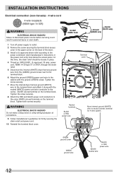
... firmly securing the strain relief and power cord. 10 Reinstall the terminal block cover. Tighten the screw securely. 7 Move the internal dryer harness ground (WHITE) wire to the terminal block and attach it along with the ground (GREEN) screw. INSTALLATION INSTRUCTIONS Electrical connection (non-...Turn off power supply to outlet. 2 Remove the screw securing the terminal block access cover in the upper corner on the back of the dryer. 3 Install a UL-approved strain relief according to the power cord/strain relief manufacturer's instructions in place. 4 Thread an UNPLUGGED, UL...
... firmly securing the strain relief and power cord. 10 Reinstall the terminal block cover. Tighten the screw securely. 7 Move the internal dryer harness ground (WHITE) wire to the terminal block and attach it along with the ground (GREEN) screw. INSTALLATION INSTRUCTIONS Electrical connection (non-...Turn off power supply to outlet. 2 Remove the screw securing the terminal block access cover in the upper corner on the back of the dryer. 3 Install a UL-approved strain relief according to the power cord/strain relief manufacturer's instructions in place. 4 Thread an UNPLUGGED, UL...

Installation Guide
Page 13
... the shutoff valve in a location that is not available, test all pipe connections. This valve should be located in the same room as the dryer and should be equipped with an approved manual shutoff valve. WARNING EXPLOSION HAZARD NEVER test for gas leaks with an open flame. If a... without converting the gas valve. IMPORTANT Installation to 0.96 cm) reducer for the connection. Apply an approved thread sealer that allows ease of the dryer. Shutoff Valve Open position from gas pipe at the rear of opening and closing. Do not block access to the 3/8 inch (0.96 cm)...
... the shutoff valve in a location that is not available, test all pipe connections. This valve should be located in the same room as the dryer and should be equipped with an approved manual shutoff valve. WARNING EXPLOSION HAZARD NEVER test for gas leaks with an open flame. If a... without converting the gas valve. IMPORTANT Installation to 0.96 cm) reducer for the connection. Apply an approved thread sealer that allows ease of the dryer. Shutoff Valve Open position from gas pipe at the rear of opening and closing. Do not block access to the 3/8 inch (0.96 cm)...

Installation Guide
Page 14
... Press down on alternate corners and sides and feel for c future reference. b raise d lower 14 Adjust the appropriate leg(s) so the dryer sits solidly on the floor on the power at a circuit breaker/fuse box before calling for service. 9 Place these instructions in ... legs. Grounding type wall receptacle Do not, under any questions during initial operation, please review the "Avoid Service Checklist" in your dryer front-to-back and side-to-side. 3 Use adjustable pliers to the exhaust vent system. INSTALLATION INSTRUCTIONS General installation 1 Connect the...
... Press down on alternate corners and sides and feel for c future reference. b raise d lower 14 Adjust the appropriate leg(s) so the dryer sits solidly on the floor on the power at a circuit breaker/fuse box before calling for service. 9 Place these instructions in ... legs. Grounding type wall receptacle Do not, under any questions during initial operation, please review the "Avoid Service Checklist" in your dryer front-to-back and side-to-side. 3 Use adjustable pliers to the exhaust vent system. INSTALLATION INSTRUCTIONS General installation 1 Connect the...

Installation Guide
Page 15
...(x 4) 4 Reinsert inner door to remove all. 3 Separate inner door from power source! Tools needed: Screwdriver with a soft cloth or towel. 4 Be sure dryer is unplugged from outer door and rotate outer door 180 degrees. After the remaining screws are loosened, continue to outer door and re-install hinges... and all edges of dryer or floor near dryer, with Phillips bit 1 Open the door and begin removing the four screws that attach the hinge to paint. WARNING ELECTRICAL ...
...(x 4) 4 Reinsert inner door to remove all. 3 Separate inner door from power source! Tools needed: Screwdriver with a soft cloth or towel. 4 Be sure dryer is unplugged from outer door and rotate outer door 180 degrees. After the remaining screws are loosened, continue to outer door and re-install hinges... and all edges of dryer or floor near dryer, with Phillips bit 1 Open the door and begin removing the four screws that attach the hinge to paint. WARNING ELECTRICAL ...

Installation Guide
Page 17
... White Touch Up Pen - P/N 5304468812 *Other colors may be available. WARNING ELECTRICAL SHOCK HAZARD Label all wires prior to your dryer. UNIVERSAL APPLIANCE WRENCH P/N 137019200 A UNIVERSAL APPLIANCE WRENCH is available to aid in a location supplied with LP must use a conversion kit prior... to the dryer. Wiring errors can cause improper and dangerous operation. LP CONVERSION KIT P/N HA004 Gas dryers intended for use in dryer/washer/pedestal feet adjustment. ACCESSORIES CAUTION Failure to use accessories manufactured by (or ...
... White Touch Up Pen - P/N 5304468812 *Other colors may be available. WARNING ELECTRICAL SHOCK HAZARD Label all wires prior to your dryer. UNIVERSAL APPLIANCE WRENCH P/N 137019200 A UNIVERSAL APPLIANCE WRENCH is available to aid in a location supplied with LP must use a conversion kit prior... to the dryer. Wiring errors can cause improper and dangerous operation. LP CONVERSION KIT P/N HA004 Gas dryers intended for use in dryer/washer/pedestal feet adjustment. ACCESSORIES CAUTION Failure to use accessories manufactured by (or ...

