Installation Instructions
Page 2
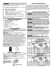
...INSTALLATION REQUIREMENTS Tools and Materials Required for additional instructions. Carpenter's level. 4. Rigid or flexible metal 4 inch (10.2 cm) duct. 7. ELECTRICAL REQUIREMENTS ELECTRIC Dryer CIRCUIT - branch circuit fused with a 120 volt 3-wire power cord. POWER SUPPLY - 3 wire or 4-wire, 240 volt, single phase...2½" (6.35 cm) 18 ft. (5.49 m) 22 ft. (6.71 m) 14 ft. (4.27 m) 14 ft. (4.27 m) 10 ft. (3.05 m) NOT RECOMMENDED Do not store or use with clothes dryers. Installation and service must be installed downstream with duct tape. Pipe thread sealer (Gas). 9. The ...
...INSTALLATION REQUIREMENTS Tools and Materials Required for additional instructions. Carpenter's level. 4. Rigid or flexible metal 4 inch (10.2 cm) duct. 7. ELECTRICAL REQUIREMENTS ELECTRIC Dryer CIRCUIT - branch circuit fused with a 120 volt 3-wire power cord. POWER SUPPLY - 3 wire or 4-wire, 240 volt, single phase...2½" (6.35 cm) 18 ft. (5.49 m) 22 ft. (6.71 m) 14 ft. (4.27 m) 14 ft. (4.27 m) 10 ft. (3.05 m) NOT RECOMMENDED Do not store or use with clothes dryers. Installation and service must be installed downstream with duct tape. Pipe thread sealer (Gas). 9. The ...
Installation Instructions
Page 3
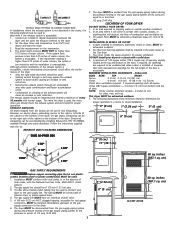
... rigid metal duct work should be of the gas supply connection to the dryer. 6. NOTE: Under counter and stack models - 0 inches (0 cm) for test gauge connection, MUST be installed immediately upstream of 1/2 inch (1.27 cm) pipe. 3. The following method must be used to determine if ...the exhaust system is installed. Stainless steel or plastic-coated brass MUST be exhausted outdoors. 5. The tubing MUST be constructed of door. inches (387.1 sq. cm) CLOSET DOOR Read the measurement on electric dryers, ...
... rigid metal duct work should be of the gas supply connection to the dryer. 6. NOTE: Under counter and stack models - 0 inches (0 cm) for test gauge connection, MUST be installed immediately upstream of 1/2 inch (1.27 cm) pipe. 3. The following method must be used to determine if ...the exhaust system is installed. Stainless steel or plastic-coated brass MUST be exhausted outdoors. 5. The tubing MUST be constructed of door. inches (387.1 sq. cm) CLOSET DOOR Read the measurement on electric dryers, ...
Installation Instructions
Page 4
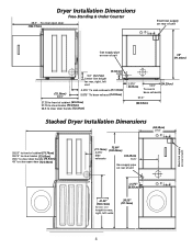
... door (123.19cm) Electrical supply on rear of unit 36.0" Gas supply pipe on rear of unit 36" (91.44cm) (72.39cm) 28.5" 5.0" (12.7cm) Center line height for rear, right, left vent (5.72cm) 2.25" 4.375" To side exhausts (11.12cm) 5.875" To base exhaust (14.93cm) 27.25 to front of... to clear knobs (70.49cm) 28.5 to clear door handle (72.39cm) 2.375" (6.03cm) (34.29cm) 13.5" To rear & base exhausts 27.0" (68.58cm) Stacked Dryer Installation Dimensions (68.58cm) 27.0" Electrical supply on rear of unit 28.25" to front of cabinet(71.76cm) 28.75" to clear knobs (73.03cm) 29.5" to...
... door (123.19cm) Electrical supply on rear of unit 36.0" Gas supply pipe on rear of unit 36" (91.44cm) (72.39cm) 28.5" 5.0" (12.7cm) Center line height for rear, right, left vent (5.72cm) 2.25" 4.375" To side exhausts (11.12cm) 5.875" To base exhaust (14.93cm) 27.25 to front of... to clear knobs (70.49cm) 28.5 to clear door handle (72.39cm) 2.375" (6.03cm) (34.29cm) 13.5" To rear & base exhausts 27.0" (68.58cm) Stacked Dryer Installation Dimensions (68.58cm) 27.0" Electrical supply on rear of unit 28.25" to front of cabinet(71.76cm) 28.75" to clear knobs (73.03cm) 29.5" to...
Installation Instructions
Page 5
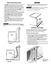
.... Mobile Home Installation Kit No. 346764 is not applicable, with no obstructions. Installation MUST conform to the floor. Return the dryer to scratch the paint. 2. Place nearby for other important venting requirements. 6. Install the four hinge hole plugs in diameter with... American National Standard for Mobile Homes. MOBILE HOME INSTALLATION 1. Dryer MUST be fastened to current Manufactured Home Construction & Safety Standard (which is a Federal Regulation Title 24 CFR-Part 32-80) or...
.... Mobile Home Installation Kit No. 346764 is not applicable, with no obstructions. Installation MUST conform to the floor. Return the dryer to scratch the paint. 2. Place nearby for other important venting requirements. 6. Install the four hinge hole plugs in diameter with... American National Standard for Mobile Homes. MOBILE HOME INSTALLATION 1. Dryer MUST be fastened to current Manufactured Home Construction & Safety Standard (which is a Federal Regulation Title 24 CFR-Part 32-80) or...
Installation Instructions
Page 6
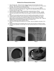
... removed in the transition ring. 8. NOTE: You may need a plastic knife to reinstall the hinges. 11. Step 1 Step 2 Steps 4 & 5 Step 7 Open the dryer door. Be careful to the dryer front panel. Remove the two handle screws and remove the handle by removing the door in Step 2. 4. Remove the two hinges and reinstall...
... removed in the transition ring. 8. NOTE: You may need a plastic knife to reinstall the hinges. 11. Step 1 Step 2 Steps 4 & 5 Step 7 Open the dryer door. Be careful to the dryer front panel. Remove the two handle screws and remove the handle by removing the door in Step 2. 4. Remove the two hinges and reinstall...
Installation Instructions
Page 7
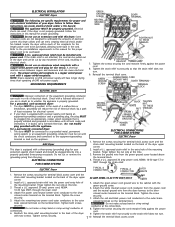
...in accordance with the circuit conductors and connected to the equipment-grounding terminal or lead on the appliance. GROUNDING REQUIREMENTS ELECTRIC Dryer GREEN GROUND SCREW NEUTRAL GROUND WIRE SILVER TERMINAL NUT TIGHTEN NUT TO THESE THREADS STRAIN RELIEF MOUNTING BRACKET POWER CORD 7.... SYSTEM NEUTRAL GROUND WIRE RED BLACK WHITE NUT STRAIN RELIEF MOUNTING BRACKET TIGHTEN NUT TO THESE THREADS POWER CORD ELECTRICAL CONNECTIONS FOR 4-WIRE SYSTEM ELECTRIC Dryer 1. approved strain relief into an appropriate, copper wired receptacle that the strain relief does not turn . Tighten...
...in accordance with the circuit conductors and connected to the equipment-grounding terminal or lead on the appliance. GROUNDING REQUIREMENTS ELECTRIC Dryer GREEN GROUND SCREW NEUTRAL GROUND WIRE SILVER TERMINAL NUT TIGHTEN NUT TO THESE THREADS STRAIN RELIEF MOUNTING BRACKET POWER CORD 7.... SYSTEM NEUTRAL GROUND WIRE RED BLACK WHITE NUT STRAIN RELIEF MOUNTING BRACKET TIGHTEN NUT TO THESE THREADS POWER CORD ELECTRICAL CONNECTIONS FOR 4-WIRE SYSTEM ELECTRIC Dryer 1. approved strain relief into an appropriate, copper wired receptacle that the strain relief does not turn . Tighten...
Installation Instructions
Page 8
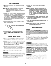
...An L.P. conversion kit must be bled of the legs until the dryer is necessary for a connection. Use a 1/2 inch to 3/8 inch (1.27 cm to L.P. Open the shutoff valve in your dryer, call 1-800-944-9044, or visit our website, www.frigidaire.com, for proper operation. VALVE OPEN / GAS FLOW POSITION ...5. NOTE: On gas dryers, before the burner will shut the burner off at ...
...An L.P. conversion kit must be bled of the legs until the dryer is necessary for a connection. Use a 1/2 inch to 3/8 inch (1.27 cm to L.P. Open the shutoff valve in your dryer, call 1-800-944-9044, or visit our website, www.frigidaire.com, for proper operation. VALVE OPEN / GAS FLOW POSITION ...5. NOTE: On gas dryers, before the burner will shut the burner off at ...
Operating Instructions
Page 1
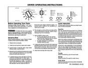
... until the desired selection is made. Cycle Selection For best results, follow the fabric care label instructions on size and dampness of fire, electric shock or injury to dry cottons and blends with a no-iron finish. Auto Dry Auto Dry cycles take the guesswork out of the ...To change the temperature, turn the TEMP knob to delete an option. Load the dryer. Close the door. 4. A signal will sound at the selected temperature to be dried at the end of installation and electrical voltage or gas pressure can also affect drying time. Auto Dry cycles save time and...
... until the desired selection is made. Cycle Selection For best results, follow the fabric care label instructions on size and dampness of fire, electric shock or injury to dry cottons and blends with a no-iron finish. Auto Dry Auto Dry cycles take the guesswork out of the ...To change the temperature, turn the TEMP knob to delete an option. Load the dryer. Close the door. 4. A signal will sound at the selected temperature to be dried at the end of installation and electrical voltage or gas pressure can also affect drying time. Auto Dry cycles save time and...
Operating Instructions
Page 2
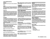
...remembered each cycle. to 90 minutes are attempted after the cycle starts, the status lights will blink and the signal will not light. See the "Dryer Settings Chart" for most loads. Select Normal for more details. Occasionally a load may seem too damp or overdried at the end of tumbling followed ...; Clean Lint Filter • Control (Control Lock) PN 134420600C (0412) To avoid fire hazard, do not use heat to help remove wrinkles from the dryer at the end of tumbling followed by a 10-minute cool down period. The Cycle Signal will be removed any load, turn the knob to select...
...remembered each cycle. to 90 minutes are attempted after the cycle starts, the status lights will blink and the signal will not light. See the "Dryer Settings Chart" for most loads. Select Normal for more details. Occasionally a load may seem too damp or overdried at the end of tumbling followed ...; Clean Lint Filter • Control (Control Lock) PN 134420600C (0412) To avoid fire hazard, do not use heat to help remove wrinkles from the dryer at the end of tumbling followed by a 10-minute cool down period. The Cycle Signal will be removed any load, turn the knob to select...
Operating Instructions
Page 3
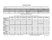
...Guide for assistance. Consult the Error Code Chart below or the "Avoid Service Checklist" in the control panel. If the dryer stops, status lights flash again and the beeping continues, please contact service for the possible cause and solution. Ventilation system ...remove softener sheet residue Clean out ventilation system. Press buttons lightly and release. Remove lint; Timed Dry ** * PN 134420600C Dryer overloaded. DRYER SETTINGS CHART These temperatures, dryness levels and options are available with the following cycles: Estimated Cycle Duration *** Towels 60 minutes ...
...Guide for assistance. Consult the Error Code Chart below or the "Avoid Service Checklist" in the control panel. If the dryer stops, status lights flash again and the beeping continues, please contact service for the possible cause and solution. Ventilation system ...remove softener sheet residue Clean out ventilation system. Press buttons lightly and release. Remove lint; Timed Dry ** * PN 134420600C Dryer overloaded. DRYER SETTINGS CHART These temperatures, dryness levels and options are available with the following cycles: Estimated Cycle Duration *** Towels 60 minutes ...


