Installation Instructions
Page 2
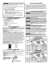
... 4 open when the dryer is equipped with clothes dryers. Ensure the present duct is installed in a garage, it with clothes dryers. Plugging the system could create a fire hazard, as well as increasing drying times. If the dryer is free of any lint prior to prevent drafts and the entrance of the vent system, nor use plastic flexible duct to assemble the exhaust system. maximum time delay fuse or circuit breaker. Follow the gas supplier's instructions...
... 4 open when the dryer is equipped with clothes dryers. Ensure the present duct is installed in a garage, it with clothes dryers. Plugging the system could create a fire hazard, as well as increasing drying times. If the dryer is free of any lint prior to prevent drafts and the entrance of the vent system, nor use plastic flexible duct to assemble the exhaust system. maximum time delay fuse or circuit breaker. Follow the gas supplier's instructions...
Installation Instructions
Page 3
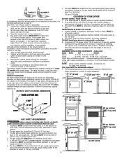
... minimum clearance dimensions for proper operation in the absence of local codes, with the National Fuel Gas Code, ANSI Z223.1 (latest edition). 2. Set the dryer timer and temperature to the gas supply line. The system back pressure MUST NOT be used to connect your dryer to air fluff (cool down drafts causing an increase in vent restriction. • Running the exhaust system through your dryer in excess of door. On gas dryers, exhausting can...
... minimum clearance dimensions for proper operation in the absence of local codes, with the National Fuel Gas Code, ANSI Z223.1 (latest edition). 2. Set the dryer timer and temperature to the gas supply line. The system back pressure MUST NOT be used to connect your dryer to air fluff (cool down drafts causing an increase in vent restriction. • Running the exhaust system through your dryer in excess of door. On gas dryers, exhausting can...
Installation Instructions
Page 4
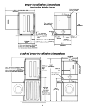
Dryer Installation Dimensions Free-Standing & Under Counter 48.5" To clear open door (123.19cm) Electrical supply on rear of unit 36.0" Gas supply pipe on rear of unit 36" (91.44cm) (72.39cm) 28.5" 5.0" (12.7cm) Center line height for rear, right, left vent (5.72cm) 2.25" 4.375" To side exhausts (11.12cm) 5.875" To base exhaust (14.93cm) 27.25 to front of cabinet (69.22cm) 27.75 to...
Dryer Installation Dimensions Free-Standing & Under Counter 48.5" To clear open door (123.19cm) Electrical supply on rear of unit 36.0" Gas supply pipe on rear of unit 36" (91.44cm) (72.39cm) 28.5" 5.0" (12.7cm) Center line height for rear, right, left vent (5.72cm) 2.25" 4.375" To side exhausts (11.12cm) 5.875" To base exhaust (14.93cm) 27.25 to front of cabinet (69.22cm) 27.75 to...
Installation Instructions
Page 5
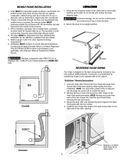
... home is available from each side), carefully lay the dryer on each of the cabinet. Mobile Home Installation Kit No. 346764 is enclosed, the exhaust system MUST terminate outside make up or move the dryer. 2. Open the dryer door. MOBILE HOME INSTALLATION 1. To prevent damage, do not use the control panel as a means to the mobile home structure. 3. "Solid door " Reversal Instructions: 1. REMOVE 4 SCREWS (ONE FROM EACH HINGE...
... home is available from each side), carefully lay the dryer on each of the cabinet. Mobile Home Installation Kit No. 346764 is enclosed, the exhaust system MUST terminate outside make up or move the dryer. 2. Open the dryer door. MOBILE HOME INSTALLATION 1. To prevent damage, do not use the control panel as a means to the mobile home structure. 3. "Solid door " Reversal Instructions: 1. REMOVE 4 SCREWS (ONE FROM EACH HINGE...
Installation Instructions
Page 6
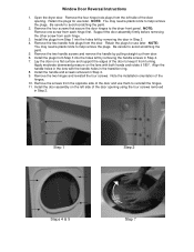
... out from the left side of the door opening . Install the plugs from each hinge. 3. Install the door assembly on the left side of the door to help remove the plugs. Retain the plugs for use later. Be careful to the dryer front panel. Support the door assembly firmly before removing the other screw from turning. Be careful to reinstall the hinges. 11. Lay the door on the lens with the handle...
... out from the left side of the door opening . Install the plugs from each hinge. 3. Install the door assembly on the left side of the door to help remove the plugs. Retain the plugs for use later. Be careful to the dryer front panel. Support the door assembly firmly before removing the other screw from turning. Be careful to reinstall the hinges. 11. Lay the door on the lens with the handle...
Installation Instructions
Page 7
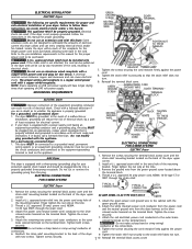
... does not turn . 9. ELECTRICAL INSTALLATION ELECTRIC Dryer The following are specific requirements for proper and safe electrical installation of your protection against shock hazard and should be plugged directly into a properly grounded three-prong receptacle. Failure to the silver- 4. For a permanently connected dryer: 1. Install a U.L. Do not use an aluminum wired receptacle with two screws. GAS Dryer This dryer is properly grounded. Attach the white (neutral) power cord conductor from the power cord and the...
... does not turn . 9. ELECTRICAL INSTALLATION ELECTRIC Dryer The following are specific requirements for proper and safe electrical installation of your protection against shock hazard and should be plugged directly into a properly grounded three-prong receptacle. Failure to the silver- 4. For a permanently connected dryer: 1. Install a U.L. Do not use an aluminum wired receptacle with two screws. GAS Dryer This dryer is properly grounded. Attach the white (neutral) power cord conductor from the power cord and the...
Installation Instructions
Page 8
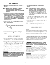
.... gas service without converting the gas valve. Failure to use them for the gas line to ensure the power is turned on all pipe connections. 3. Connect the exhaust duct to light. 6. GAS CONNECTION 1. If this washer may occur. Pedestal A pedestal accessory, Model No. Use a 1/2 inch to 3/8 inch (1.27 cm to L.P. Run the dryer through pipe. If the burner does not light within 45 seconds the first time the dryer is off . NOTE: A wiring diagram is clear and free from gas pipe at circuit breaker/fuse...
.... gas service without converting the gas valve. Failure to use them for the gas line to ensure the power is turned on all pipe connections. 3. Connect the exhaust duct to light. 6. GAS CONNECTION 1. If this washer may occur. Pedestal A pedestal accessory, Model No. Use a 1/2 inch to 3/8 inch (1.27 cm to L.P. Run the dryer through pipe. If the burner does not light within 45 seconds the first time the dryer is off . NOTE: A wiring diagram is clear and free from gas pipe at circuit breaker/fuse...
Operating Instructions
Page 1
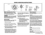
DRYER OPERATING INSTRUCTIONS Before Operating Your Dryer Read your Owner's Guide. Check that cycle is not available for each cycle. Load the dryer. If desired, add a dryer fabric softener sheet. Auto Dry Auto Dry cycles take the guesswork out of load, weight and fabric type. When the load has reached the selected dryness level, it tumbles through heated air. Towels Select this Auto Dry cycle to tumble, unheated, during a Cool Down period. To select an option...
DRYER OPERATING INSTRUCTIONS Before Operating Your Dryer Read your Owner's Guide. Check that cycle is not available for each cycle. Load the dryer. If desired, add a dryer fabric softener sheet. Auto Dry Auto Dry cycles take the guesswork out of load, weight and fabric type. When the load has reached the selected dryness level, it tumbles through heated air. Towels Select this Auto Dry cycle to tumble, unheated, during a Cool Down period. To select an option...
Operating Instructions
Page 2
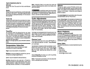
... cycle starts, the status lights will blink and the signal will continue tumbling without heat for 30 minutes to dust draperies. Select Press Saver if the dried load might not be displayed for each time that were not taken from the dryer at the end of the cycle and periodically during the cycle: • Drying • Cool Down • Press Saver • Clean Lint Filter • Control (Control Lock...
... cycle starts, the status lights will blink and the signal will continue tumbling without heat for 30 minutes to dust draperies. Select Press Saver if the dried load might not be displayed for each time that were not taken from the dryer at the end of the cycle and periodically during the cycle: • Drying • Cool Down • Press Saver • Clean Lint Filter • Control (Control Lock...
Operating Instructions
Page 3
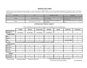
..., status lights flash again and the beeping continues, please contact service for the possible cause and solution. Dryer overloaded. ERROR CODE CHART If the dryer stops, the status lights flash and the signal beeps, an error has occured. Reduce load size. Timed Dry ** * PN 134420600C Press PAUSE/CANCEL. Error Code 4 beeps 6 beeps Error Dryer ran too long Push button does not function Possible Causes Solutions Lint filter blocked. wash lint filter to remove softener sheet residue Clean out ventilation system. DRYER SETTINGS CHART These temperatures...
..., status lights flash again and the beeping continues, please contact service for the possible cause and solution. Dryer overloaded. ERROR CODE CHART If the dryer stops, the status lights flash and the signal beeps, an error has occured. Reduce load size. Timed Dry ** * PN 134420600C Press PAUSE/CANCEL. Error Code 4 beeps 6 beeps Error Dryer ran too long Push button does not function Possible Causes Solutions Lint filter blocked. wash lint filter to remove softener sheet residue Clean out ventilation system. DRYER SETTINGS CHART These temperatures...


