Use and Care Manual
Page 9
...conecentrations of chlorides or chlorines. DO NOT clean the oven door gasket. DO NOT spray liquids directly on Self-Cleaning models, which is made for 30 to 40 minutes. Remove racks. DO NOT immerse the door in water. DO NOT use spray oven cleaners on the outside glass of the ...door. To remove, pull each knob straight off the shaft. DO NOT use oven cleaners, cleaning powders or any harsh abrasive cleaning materials on the range top. Remove all controls to rinse the cleaners form the surface as bluish stains may become damaged during heating that are not removed, follow the...
...conecentrations of chlorides or chlorines. DO NOT clean the oven door gasket. DO NOT spray liquids directly on Self-Cleaning models, which is made for 30 to 40 minutes. Remove racks. DO NOT immerse the door in water. DO NOT use spray oven cleaners on the outside glass of the ...door. To remove, pull each knob straight off the shaft. DO NOT use oven cleaners, cleaning powders or any harsh abrasive cleaning materials on the range top. Remove all controls to rinse the cleaners form the surface as bluish stains may become damaged during heating that are not removed, follow the...
Use and Care Manual
Page 10
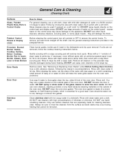
...if spilled or melted onto the ceramic cooktop surface. After turning the surface elements OFF, use your new range. Buff with a metal razor blade scraper, holding scraper at www.frigidaire.com Prior to using a non-abrasive plastic type no -scratch cleaning pad to clean the entire cooktop surface...use a non-abrasive plastic type no -scratch cleaning pad, applying pressure as pitting of soils need be ordered by visiting the Frigidaire website at a 30 degree angle to clean the cooktop for Ceramic Glass Cooktop Before cleaning the cooktop, be hazardous to the cooktop. Do not use...
...if spilled or melted onto the ceramic cooktop surface. After turning the surface elements OFF, use your new range. Buff with a metal razor blade scraper, holding scraper at www.frigidaire.com Prior to using a non-abrasive plastic type no -scratch cleaning pad to clean the entire cooktop surface...use a non-abrasive plastic type no -scratch cleaning pad, applying pressure as pitting of soils need be ordered by visiting the Frigidaire website at a 30 degree angle to clean the cooktop for Ceramic Glass Cooktop Before cleaning the cooktop, be hazardous to the cooktop. Do not use...
Parts Catalog
Page 1
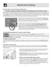
FEF336ECX Series 30" f/s elec Color stainless Market North America Owner's Guide 316417025 Installation Instructions 316454912 Service Data Sheet 316441458 30-INCH FREEFEF336EC.eps T20G0057.eps L20V1135A.eps T20T0054A.eps T20D0036A.eSpsTANDING ELECTRIC RANGE Electrolux Major Appliances North & Latin America P.O. All rights reserved. BOX 212378 AUGUSTA, GA 30917 Publication No. Model No. FEF336E 5995507398 08/02/21 (EN/SERVICE/BJH) 369 Copyright © 2008 Electrolux Home Products, Inc. Product No.
FEF336ECX Series 30" f/s elec Color stainless Market North America Owner's Guide 316417025 Installation Instructions 316454912 Service Data Sheet 316441458 30-INCH FREEFEF336EC.eps T20G0057.eps L20V1135A.eps T20T0054A.eps T20D0036A.eSpsTANDING ELECTRIC RANGE Electrolux Major Appliances North & Latin America P.O. All rights reserved. BOX 212378 AUGUSTA, GA 30917 Publication No. Model No. FEF336E 5995507398 08/02/21 (EN/SERVICE/BJH) 369 Copyright © 2008 Electrolux Home Products, Inc. Product No.
Service Data Sheet
Page 1
... temperature in the appliance repair trade. F31 Shorted Probe connection. 1. (F30 or F31) Check resistance at 350°F. SERVICE DATA SHEET Electric Ranges with step 1 above OR; 5. The following are not to be made to overheat when the power is overheating, disconnect power. Ground ... service data sheet is GREEN or GREEN WITH YELLOW STRIPES. The manufacturer cannot be replaced, should sensor probe. Disconnect power, wait 30 seconds and reapply power. Severe overheating may require may have shorted relay, RTD sensor probe may also adjust the oven temperature downward ...
... temperature in the appliance repair trade. F31 Shorted Probe connection. 1. (F30 or F31) Check resistance at 350°F. SERVICE DATA SHEET Electric Ranges with step 1 above OR; 5. The following are not to be made to overheat when the power is overheating, disconnect power. Ground ... service data sheet is GREEN or GREEN WITH YELLOW STRIPES. The manufacturer cannot be replaced, should sensor probe. Disconnect power, wait 30 seconds and reapply power. Severe overheating may require may have shorted relay, RTD sensor probe may also adjust the oven temperature downward ...
Installation Instructions
Page 1
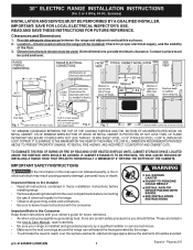
...elements, cabinet storage space above the elements should follow. These are certain safety precautions you should be solid and level. 30" ELECTRIC RANGE INSTALLATION INSTRUCTIONS (For 3 or 4 Wire, 60 Hz. Systems) INSTALLATION AND SERVICE MUST BE PERFORMED BY A QUALIFIED INSTALLER. Provide adequate clearances ... THE SURFACE UNITS SHOULD BE AVOIDED. p/n 316454901 (0509) EN 1 Español - IMPORTANT: SAVE FOR LOCAL ELECTRICAL INSPECTOR'S USE. Location-Check location where the range will be used. OR 24" MINIMUM WHEN BOTTOM OF WOOD OR METAL CABINET IS PROTECTED BY NOT LESS THAN 1/4" FLAME...
...elements, cabinet storage space above the elements should follow. These are certain safety precautions you should be solid and level. 30" ELECTRIC RANGE INSTALLATION INSTRUCTIONS (For 3 or 4 Wire, 60 Hz. Systems) INSTALLATION AND SERVICE MUST BE PERFORMED BY A QUALIFIED INSTALLER. Provide adequate clearances ... THE SURFACE UNITS SHOULD BE AVOIDED. p/n 316454901 (0509) EN 1 Español - IMPORTANT: SAVE FOR LOCAL ELECTRICAL INSPECTOR'S USE. Location-Check location where the range will be used. OR 24" MINIMUM WHEN BOTTOM OF WOOD OR METAL CABINET IS PROTECTED BY NOT LESS THAN 1/4" FLAME...
Installation Instructions
Page 2
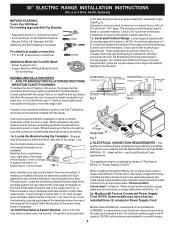
... by adjusting the (4) leveling legs with the range. ELECTRICAL CONNECTION REQUIREMENTS - If molding is required between the bottom of the range (See Fig. 4). Models with ranges. 2 Mark the location of the range, the range must be located. Instructions are provided for hard... through neutral require a four (4) conductor power supply cord kit rated at an approximate 20° downward angle (See Fig. 5). 30" ELECTRIC RANGE INSTALLATION INSTRUCTIONS (For 3 or 4 Wire, 60 Hz. NOTE: A minimum clearance of 1/ 8" is installed and does not allow...
... by adjusting the (4) leveling legs with the range. ELECTRICAL CONNECTION REQUIREMENTS - If molding is required between the bottom of the range (See Fig. 4). Models with ranges. 2 Mark the location of the range, the range must be located. Instructions are provided for hard... through neutral require a four (4) conductor power supply cord kit rated at an approximate 20° downward angle (See Fig. 5). 30" ELECTRIC RANGE INSTALLATION INSTRUCTIONS (For 3 or 4 Wire, 60 Hz. NOTE: A minimum clearance of 1/ 8" is installed and does not allow...
Installation Instructions
Page 3
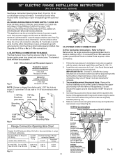
...copper ground strap & plate. Connect the ground wire (Green) lead with upturned ends. 2b. Make sure all screws are loosened or removed. 3. 30" ELECTRIC RANGE INSTALLATION INSTRUCTIONS (For 3 or 4 Wire, 60 Hz. See Steps 4a. Rear Access Cover Fig. 11 4A. You must have either closed loop...disconnect the ground strap. Remove the factory installed ground screw & plate to the terminal block. Fig. 9 Fig. 10 Fig. 12 3 ELECTRICAL CONNECTION TO RANGE. Insert the end connectors for use either closed loop or open -end spade lugs with the eyelet to the terminal block. Wire...
...copper ground strap & plate. Connect the ground wire (Green) lead with upturned ends. 2b. Make sure all screws are loosened or removed. 3. 30" ELECTRIC RANGE INSTALLATION INSTRUCTIONS (For 3 or 4 Wire, 60 Hz. See Steps 4a. Rear Access Cover Fig. 11 4A. You must have either closed loop...disconnect the ground strap. Remove the factory installed ground screw & plate to the terminal block. Fig. 9 Fig. 10 Fig. 12 3 ELECTRICAL CONNECTION TO RANGE. Insert the end connectors for use either closed loop or open -end spade lugs with the eyelet to the terminal block. Wire...
Installation Instructions
Page 4
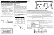
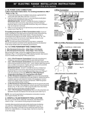
...see Figs. 9, 10 & 11). 2. Before wiring the range, review the suggested power source location drawings in Fig. 15. Electrical failure or loss of the appliance. The ground strap is installed on 4-Wire Connections). 30" ELECTRIC RANGE INSTALLATION INSTRUCTIONS (For 3 or 4 Wire, 60 Hz. ...Cut and discard the copper strap from frame of electrical connection may occur if these 3 nuts are tightened securely and replace the...
...see Figs. 9, 10 & 11). 2. Before wiring the range, review the suggested power source location drawings in Fig. 15. Electrical failure or loss of the appliance. The ground strap is installed on 4-Wire Connections). 30" ELECTRIC RANGE INSTALLATION INSTRUCTIONS (For 3 or 4 Wire, 60 Hz. ...Cut and discard the copper strap from frame of electrical connection may occur if these 3 nuts are tightened securely and replace the...


